HP Mini 210-1000 HP Mini 2102, HP Mini 210, and Compaq Mini 210 - Maintenance - Page 61
Release the top cover, by lifting the rear edge until it disengages from the base enclosure.
 |
View all HP Mini 210-1000 manuals
Add to My Manuals
Save this manual to your list of manuals |
Page 61 highlights
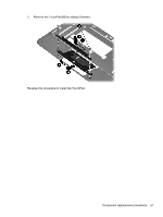
6. Release the ZIF connector (2) to which the TouchPad cable is connected, and then disconnect the TouchPad cable (3) from the system board. 7. Remove the five Phillips PM2.0×6.0 screws that secure the top cover to the base enclosure. 8. Release the top cover (1) by lifting the rear edge until it disengages from the base enclosure. Component replacement procedures 53
-
 1
1 -
2
-
3
-
4
-
5
-
6
-
7
-
8
-
9
-
10
-
11
-
12
-
13
-
14
-
15
-
16
-
17
-
18
-
19
-
20
-
21
-
22
-
23
-
24
-
25
-
26
-
27
-
28
-
29
-
30
-
31
-
32
-
33
-
34
-
35
-
36
-
37
-
38
-
39
-
40
-
41
-
42
-
43
-
44
-
45
-
46
-
47
-
48
-
49
-
50
-
51
-
52
-
53
-
54
-
55
-
 56
56 -
 57
57 -
 58
58 -
 59
59 -
 60
60 -
 61
61 -
 62
62 -
 63
63 -
 64
64 -
 65
65 -
 66
66 -
67
-
68
-
69
-
70
-
71
-
72
-
73
-
74
-
75
-
76
-
77
-
78
-
79
-
80
-
81
-
82
-
83
-
84
-
85
-
86
-
87
-
88
-
89
-
90
-
91
-
92
-
93
-
94
-
95
-
96
-
97
-
98
-
99
-
100
-
101
-
102
-
103
-
104
-
105
 |
 |

6.
Release the ZIF connector
(2)
to which the TouchPad cable is connected, and then disconnect
the TouchPad cable
(3)
from the system board.
7.
Remove the five Phillips PM2.0×6.0 screws that secure the top cover to the base enclosure.
8.
Release the top cover
(1)
by lifting the rear edge until it disengages from the base enclosure.
Component replacement procedures
53