HP Mini 210-1000 HP Mini 2102, HP Mini 210, and Compaq Mini 210 - Maintenance - Page 73
Power connector cable, System board see
 |
View all HP Mini 210-1000 manuals
Add to My Manuals
Save this manual to your list of manuals |
Page 73 highlights
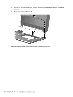
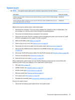
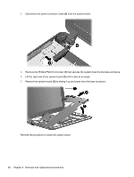
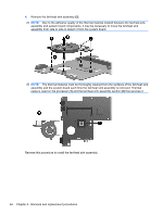
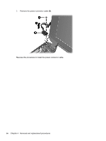
Power connector cable Description Power connector cable Spare part number 589682-001 Before removing the power connector cable, follow these steps: 1. Shut down the computer. If you are unsure whether the computer is off or in Hibernation, turn the computer on, and then shut it down through the operating system. 2. Disconnect all external devices connected to the computer. 3. Disconnect the power from the computer by first unplugging the power cord from the AC outlet and then unplugging the AC adapter from the computer. 4. Remove the battery (see Battery on page 38). 5. Remove the service cover (see Service cover on page 40). 6. Disconnect the hard drive cable from the system board (see Hard drive on page 41). 7. Disconnect the WWAN antenna cables from the WWAN module (see WWAN module on page 43). 8. Disconnect the WLAN antenna cables from the WLAN module (see WLAN module on page 45). 9. Remove the following components: a. Keyboard (see Keyboard on page 49). b. Top cover (see Top cover on page 52). c. Display assembly (see Display assembly on page 58). d. System board (see System board on page 61). Remove the power connector cable: 1. Remove the Phillips PM2.0×4.0 screw (1) that secures the power connector and bracket to the base enclosure. 2. Remove the power connector bracket (2). NOTE: The power connector bracket is included in the base enclosure spare part kit, spare part number 589678-001. Component replacement procedures 65
-
 1
1 -
2
-
3
-
4
-
5
-
6
-
7
-
8
-
9
-
10
-
11
-
12
-
13
-
14
-
15
-
16
-
17
-
18
-
19
-
20
-
21
-
22
-
23
-
24
-
25
-
26
-
27
-
28
-
29
-
30
-
31
-
32
-
33
-
34
-
35
-
36
-
37
-
38
-
39
-
40
-
41
-
42
-
43
-
44
-
45
-
46
-
47
-
48
-
49
-
50
-
51
-
52
-
53
-
54
-
55
-
56
-
57
-
58
-
59
-
60
-
61
-
62
-
63
-
64
-
65
-
66
-
67
-
 68
68 -
 69
69 -
 70
70 -
 71
71 -
 72
72 -
 73
73 -
 74
74 -
 75
75 -
 76
76 -
 77
77 -
 78
78 -
79
-
80
-
81
-
82
-
83
-
84
-
85
-
86
-
87
-
88
-
89
-
90
-
91
-
92
-
93
-
94
-
95
-
96
-
97
-
98
-
99
-
100
-
101
-
102
-
103
-
104
-
105
 |
 |
