HP Mini 210-1000 HP Mini 2102, HP Mini 210, and Compaq Mini 210 - Maintenance - Page 70
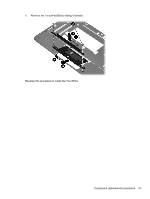
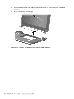
Remove the Phillips PM2.0×4.0 screw, by sliding it up and away from the base enclosure.
 |
View all HP Mini 210-1000 manuals
Add to My Manuals
Save this manual to your list of manuals |
Page 70 highlights
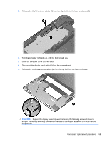
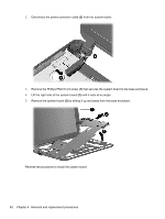
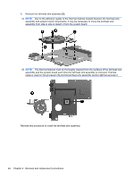
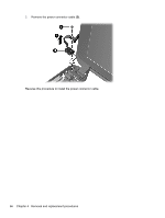
2. Disconnect the power connector cable (2) from the system board. 3. Remove the Phillips PM2.0×4.0 screw (1) that secures the system board to the base enclosure. 4. Lift the right side of the system board (2) until it rests at an angle. 5. Remove the system board (3) by sliding it up and away from the base enclosure. Reverse the procedure to install the system board. 62 Chapter 4 Removal and replacement procedures
-
 1
1 -
2
-
3
-
4
-
5
-
6
-
7
-
8
-
9
-
10
-
11
-
12
-
13
-
14
-
15
-
16
-
17
-
18
-
19
-
20
-
21
-
22
-
23
-
24
-
25
-
26
-
27
-
28
-
29
-
30
-
31
-
32
-
33
-
34
-
35
-
36
-
37
-
38
-
39
-
40
-
41
-
42
-
43
-
44
-
45
-
46
-
47
-
48
-
49
-
50
-
51
-
52
-
53
-
54
-
55
-
56
-
57
-
58
-
59
-
60
-
61
-
62
-
63
-
64
-
 65
65 -
 66
66 -
 67
67 -
 68
68 -
 69
69 -
 70
70 -
 71
71 -
 72
72 -
 73
73 -
 74
74 -
 75
75 -
76
-
77
-
78
-
79
-
80
-
81
-
82
-
83
-
84
-
85
-
86
-
87
-
88
-
89
-
90
-
91
-
92
-
93
-
94
-
95
-
96
-
97
-
98
-
99
-
100
-
101
-
102
-
103
-
104
-
105
 |
 |

2.
Disconnect the power connector cable
(2)
from the system board.
3.
Remove the Phillips PM2.0×4.0 screw
(1)
that secures the system board to the base enclosure.
4.
Lift the right side of the system board
(2)
until it rests at an angle.
5.
Remove the system board
(3)
by sliding it up and away from the base enclosure.
Reverse the procedure to install the system board.
62
Chapter 4
Removal and replacement procedures