HP Mini 210-1000 HP Mini 2102, HP Mini 210, and Compaq Mini 210 - Maintenance - Page 69
System board, WWAN module see
 |
View all HP Mini 210-1000 manuals
Add to My Manuals
Save this manual to your list of manuals |
Page 69 highlights
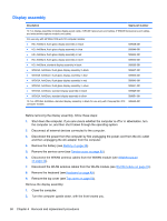
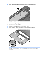
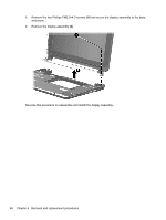
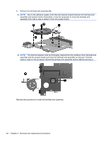
System board NOTE: The system board spare part kit includes replacement thermal material. Description Spare part number Includes Intel Atom N450 1.66-GHz processor with 512-KB level 2 cache, 667-MHz FSB and Digital 589638-001 Media Card Reader Includes Intel Atom N450 1.66-GHz processor with 512-KB level 2 cache, 667-MHz FSB, but does 589639-001 not include Digital Media Card Reader Before removing the system board, follow these steps: 1. Shut down the computer. If you are unsure whether the computer is off or in Hibernation, turn the computer on, and then shut it down through the operating system. 2. Disconnect all external devices connected to the computer. 3. Disconnect the power from the computer by first unplugging the power cord from the AC outlet and then unplugging the AC adapter from the computer. 4. Remove the battery (see Battery on page 38). 5. Remove the service cover (see Service cover on page 40). 6. Disconnect the hard drive cable from the system board (see Hard drive on page 41). 7. Disconnect the WWAN antenna cables from the WWAN module (see WWAN module on page 43). 8. Disconnect the WLAN antenna cables from the WLAN module (see WLAN module on page 45). 9. Remove the keyboard (see Keyboard on page 49). 10. Remove the top cover (see Top cover on page 52). When replacing the system board, be sure that the following components are removed from the defective system board and installed on the replacement system board: ● SIM (see SIM on page 39) ● WWAN module (see WWAN module on page 43) ● WLAN module (see WLAN module on page 45) ● Memory module (see Memory module on page 47) ● RTC battery (see RTC battery on page 48) ● Fan/heat sink assembly (see Fan/heat sink assembly on page 63) Remove the system board: 1. Disconnect the display panel cable (1) from the system board. Component replacement procedures 61
-
 1
1 -
2
-
3
-
4
-
5
-
6
-
7
-
8
-
9
-
10
-
11
-
12
-
13
-
14
-
15
-
16
-
17
-
18
-
19
-
20
-
21
-
22
-
23
-
24
-
25
-
26
-
27
-
28
-
29
-
30
-
31
-
32
-
33
-
34
-
35
-
36
-
37
-
38
-
39
-
40
-
41
-
42
-
43
-
44
-
45
-
46
-
47
-
48
-
49
-
50
-
51
-
52
-
53
-
54
-
55
-
56
-
57
-
58
-
59
-
60
-
61
-
62
-
63
-
 64
64 -
 65
65 -
 66
66 -
 67
67 -
 68
68 -
 69
69 -
 70
70 -
 71
71 -
 72
72 -
 73
73 -
 74
74 -
75
-
76
-
77
-
78
-
79
-
80
-
81
-
82
-
83
-
84
-
85
-
86
-
87
-
88
-
89
-
90
-
91
-
92
-
93
-
94
-
95
-
96
-
97
-
98
-
99
-
100
-
101
-
102
-
103
-
104
-
105
 |
 |
