HP Mini 210-1000 HP Mini 2102, HP Mini 210, and Compaq Mini 210 - Maintenance - Page 67
from the clip built into the base enclosure.
 |
View all HP Mini 210-1000 manuals
Add to My Manuals
Save this manual to your list of manuals |
Page 67 highlights
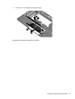
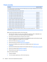
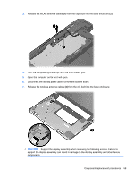
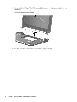
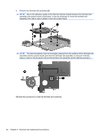
3. Release the WLAN antenna cables (1) from the clips built into the base enclosure (2). 4. Turn the computer right-side up, with the front toward you. 5. Open the computer as far as it will open. 6. Disconnect the display panel cable (1) from the system board. 7. Release the wireless antenna cables (2) from the clip built into the base enclosure. CAUTION: Support the display assembly when removing the following screws. Failure to support the display assembly can result in damage to the display assembly and other device components. Component replacement procedures 59
-
 1
1 -
2
-
3
-
4
-
5
-
6
-
7
-
8
-
9
-
10
-
11
-
12
-
13
-
14
-
15
-
16
-
17
-
18
-
19
-
20
-
21
-
22
-
23
-
24
-
25
-
26
-
27
-
28
-
29
-
30
-
31
-
32
-
33
-
34
-
35
-
36
-
37
-
38
-
39
-
40
-
41
-
42
-
43
-
44
-
45
-
46
-
47
-
48
-
49
-
50
-
51
-
52
-
53
-
54
-
55
-
56
-
57
-
58
-
59
-
60
-
61
-
 62
62 -
 63
63 -
 64
64 -
 65
65 -
 66
66 -
 67
67 -
 68
68 -
 69
69 -
 70
70 -
 71
71 -
 72
72 -
73
-
74
-
75
-
76
-
77
-
78
-
79
-
80
-
81
-
82
-
83
-
84
-
85
-
86
-
87
-
88
-
89
-
90
-
91
-
92
-
93
-
94
-
95
-
96
-
97
-
98
-
99
-
100
-
101
-
102
-
103
-
104
-
105
 |
 |

3.
Release the WLAN antenna cables
(1)
from the clips built into the base enclosure
(2)
.
4.
Turn the computer right-side up, with the front toward you.
5.
Open the computer as far as it will open.
6.
Disconnect the display panel cable
(1)
from the system board.
7.
Release the wireless antenna cables
(2)
from the clip built into the base enclosure.
CAUTION:
Support the display assembly when removing the following screws. Failure to
support the display assembly can result in damage to the display assembly and other device
components.
Component replacement procedures
59