HP Nc2400 HP Compaq nc2400 Notebook PC - Maintenance and Service Guide - Page 127
Display Assembly, Display Assembly Spare Part Number Information
 |
UPC - 883585088331
View all HP Nc2400 manuals
Add to My Manuals
Save this manual to your list of manuals |
Page 127 highlights
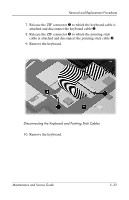
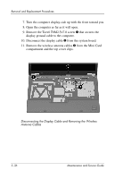
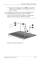
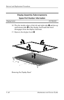
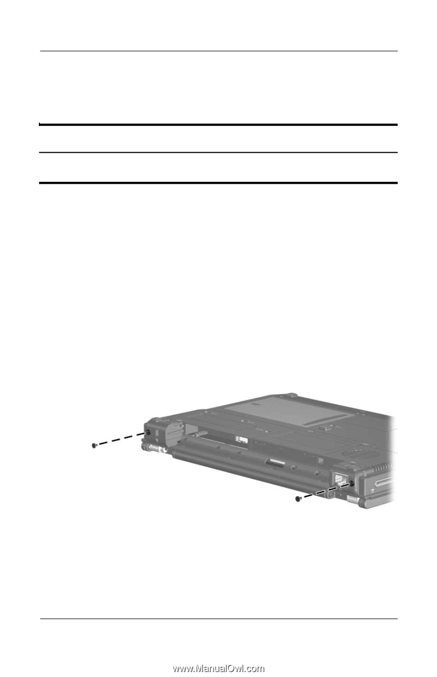
Removal and Replacement Procedures 5.13 Display Assembly Display Assembly Spare Part Number Information 12.1-inch, WXGA, TFT display assembly (includes wireless antenna transceivers and cables) 412767-001 1. Prepare the computer for disassembly (Section 5.3). 2. Disconnect the wireless antenna cables from the Mini Card WLAN module (Section 5.7). 3. Remove the switch cover (Section 5.11). 4. Remove the keyboard (Section 5.12). 5. Close the computer and turn it upside down with the rear panel toward you. 6. Remove the two Torx8 T8M2.5×7.0 screws that secure the display assembly to the computer. Removing the Display Assembly Screws Maintenance and Service Guide 5-35
-
 1
1 -
2
-
3
-
4
-
5
-
6
-
7
-
8
-
9
-
10
-
11
-
12
-
13
-
14
-
15
-
16
-
17
-
18
-
19
-
20
-
21
-
22
-
23
-
24
-
25
-
26
-
27
-
28
-
29
-
30
-
31
-
32
-
33
-
34
-
35
-
36
-
37
-
38
-
39
-
40
-
41
-
42
-
43
-
44
-
45
-
46
-
47
-
48
-
49
-
50
-
51
-
52
-
53
-
54
-
55
-
56
-
57
-
58
-
59
-
60
-
61
-
62
-
63
-
64
-
65
-
66
-
67
-
68
-
69
-
70
-
71
-
72
-
73
-
74
-
75
-
76
-
77
-
78
-
79
-
80
-
81
-
82
-
83
-
84
-
85
-
86
-
87
-
88
-
89
-
90
-
91
-
92
-
93
-
94
-
95
-
96
-
97
-
98
-
99
-
100
-
101
-
102
-
103
-
104
-
105
-
106
-
107
-
108
-
109
-
110
-
111
-
112
-
113
-
114
-
115
-
116
-
117
-
118
-
119
-
120
-
121
-
 122
122 -
 123
123 -
 124
124 -
 125
125 -
 126
126 -
 127
127 -
 128
128 -
 129
129 -
 130
130 -
 131
131 -
 132
132 -
133
-
134
-
135
-
136
-
137
-
138
-
139
-
140
-
141
-
142
-
143
-
144
-
145
-
146
-
147
-
148
-
149
-
150
-
151
-
152
-
153
-
154
-
155
-
156
-
157
-
158
-
159
-
160
-
161
-
162
-
163
-
164
-
165
-
166
-
167
-
168
-
169
-
170
-
171
-
172
-
173
-
174
-
175
-
176
-
177
-
178
-
179
-
180
-
181
-
182
-
183
-
184
-
185
-
186
-
187
-
188
-
189
-
190
-
191
-
192
-
193
-
194
-
195
-
196
-
197
-
198
-
199
-
200
-
201
-
202
-
203
-
204
-
205
-
206
-
207
-
208
-
209
-
210
-
211
-
212
-
213
-
214
-
215
-
216
-
217
-
218
-
219
-
220
-
221
-
222
-
223
-
224
-
225
-
226
-
227
-
228
-
229
-
230
 |
 |
Removal and Replacement Procedures
Maintenance and Service Guide
5–35
5.13
Display Assembly
1. Prepare the computer for disassembly (
Section 5.3
).
2. Disconnect the wireless antenna cables from the Mini Card
WLAN module (
Section 5.7
).
3. Remove the switch cover (
Section 5.11)
.
4. Remove the keyboard (
Section 5.12)
.
5. Close the computer and turn it upside down with the
rear panel toward you.
6. Remove the two Torx8 T8M2.5×7.0 screws that secure the
display assembly to the computer.
Removing the Display Assembly Screws
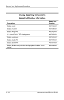
Display Assembly Spare Part Number Information
12.1-inch, WXGA, TFT display assembly (includes wireless
antenna transceivers and cables)
412767-001