HP Nc2400 HP Compaq nc2400 Notebook PC - Maintenance and Service Guide - Page 96
Description, of Screws Removed
 |
UPC - 883585088331
View all HP Nc2400 manuals
Add to My Manuals
Save this manual to your list of manuals |
Page 96 highlights
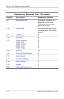
Removal and Replacement Procedures Disassembly Sequence Chart (Continued) Section 5.9 Description Bluetooth Module 5.10 Optical Drive 5.11 Switch Cover 5.12 Keyboard 5.13 Display Assembly Display bezel Display inverter Display panel Display hinges 5.14 Top Cover 5.15 Fingerprint Reader Board 5.16 System Board 5.17 PC Card Assembly 5.18 Modem Module 5.19 Speaker 5.20 Fan/Heat Sink Assembly # of Screws Removed 1 loosened to remove the Bluetooth module cover 1 removed to remove the Bluetooth module 2 to remove the optical drive 2 to remove the optical drive bracket 0 5 5 6 0 4 4 11 2 5 0 2 1 1 5-4 Maintenance and Service Guide
-
 1
1 -
2
-
3
-
4
-
5
-
6
-
7
-
8
-
9
-
10
-
11
-
12
-
13
-
14
-
15
-
16
-
17
-
18
-
19
-
20
-
21
-
22
-
23
-
24
-
25
-
26
-
27
-
28
-
29
-
30
-
31
-
32
-
33
-
34
-
35
-
36
-
37
-
38
-
39
-
40
-
41
-
42
-
43
-
44
-
45
-
46
-
47
-
48
-
49
-
50
-
51
-
52
-
53
-
54
-
55
-
56
-
57
-
58
-
59
-
60
-
61
-
62
-
63
-
64
-
65
-
66
-
67
-
68
-
69
-
70
-
71
-
72
-
73
-
74
-
75
-
76
-
77
-
78
-
79
-
80
-
81
-
82
-
83
-
84
-
85
-
86
-
87
-
88
-
89
-
90
-
 91
91 -
 92
92 -
 93
93 -
 94
94 -
 95
95 -
 96
96 -
 97
97 -
 98
98 -
 99
99 -
 100
100 -
 101
101 -
102
-
103
-
104
-
105
-
106
-
107
-
108
-
109
-
110
-
111
-
112
-
113
-
114
-
115
-
116
-
117
-
118
-
119
-
120
-
121
-
122
-
123
-
124
-
125
-
126
-
127
-
128
-
129
-
130
-
131
-
132
-
133
-
134
-
135
-
136
-
137
-
138
-
139
-
140
-
141
-
142
-
143
-
144
-
145
-
146
-
147
-
148
-
149
-
150
-
151
-
152
-
153
-
154
-
155
-
156
-
157
-
158
-
159
-
160
-
161
-
162
-
163
-
164
-
165
-
166
-
167
-
168
-
169
-
170
-
171
-
172
-
173
-
174
-
175
-
176
-
177
-
178
-
179
-
180
-
181
-
182
-
183
-
184
-
185
-
186
-
187
-
188
-
189
-
190
-
191
-
192
-
193
-
194
-
195
-
196
-
197
-
198
-
199
-
200
-
201
-
202
-
203
-
204
-
205
-
206
-
207
-
208
-
209
-
210
-
211
-
212
-
213
-
214
-
215
-
216
-
217
-
218
-
219
-
220
-
221
-
222
-
223
-
224
-
225
-
226
-
227
-
228
-
229
-
230
 |
 |
5–4
Maintenance and Service Guide
Removal and Replacement Procedures
Section
Description
# of Screws Removed
5.9
Bluetooth Module
1 loosened to remove the
Bluetooth module cover
1 removed to remove the
Bluetooth module
5.10
Optical Drive
2 to remove the optical drive
2 to remove the optical drive
bracket
5.11
Switch Cover
0
5.12
Keyboard
5
5.13
Display Assembly
Display bezel
Display inverter
Display panel
Display hinges
5
6
0
4
4
5.14
Top Cover
11
5.15
Fingerprint Reader Board
2
5.16
System Board
5
5.17
PC Card Assembly
0
5.18
Modem Module
2
5.19
Speaker
1
5.20
Fan/Heat Sink Assembly
1
Disassembly Sequence Chart
(Continued)