HP Nx7400 HP Compaq nx7300 and nx7400 Notebook PC Maintenance and Service Guid - Page 127
Memory modules are designed with a notch, incorrect installation into the memory module socket.
 |
UPC - 882780786653
View all HP Nx7400 manuals
Add to My Manuals
Save this manual to your list of manuals |
Page 127 highlights
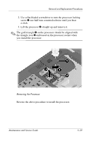
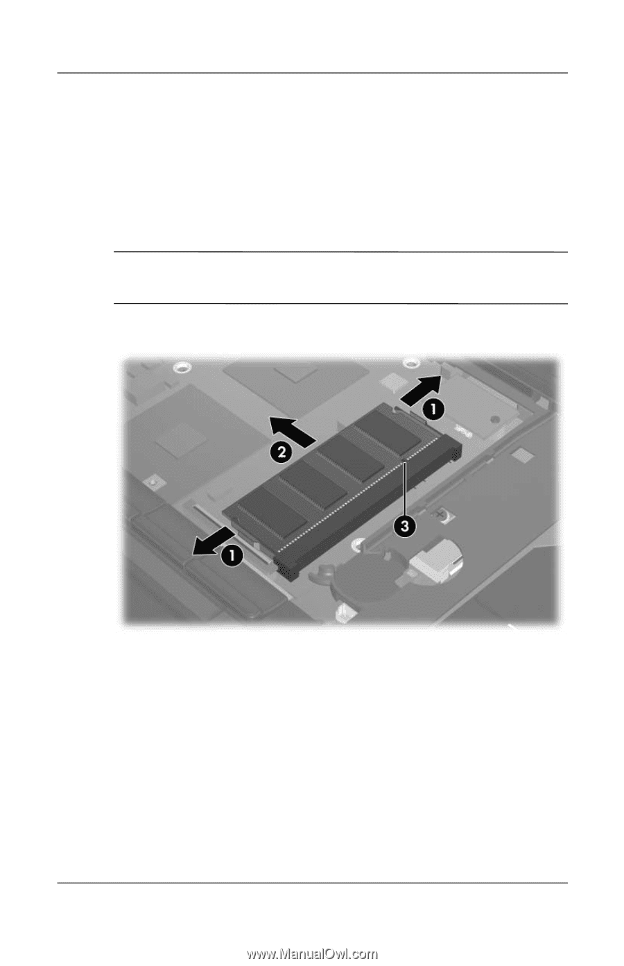
Removal and Replacement Procedures 3. Spread the retaining tabs 1 on each side of the memory module socket to release the memory module board. (The side of the module opposite the socket rises away from the computer.) 4. Slide the module away from the socket at an angle 2. 5. Remove the memory module. ✎ Memory modules are designed with a notch 3 to prevent incorrect installation into the memory module socket. Removing the Internal Memory Module Reverse the above procedure to install an internal memory module. 5-34 Maintenance and Service Guide
-
 1
1 -
2
-
3
-
4
-
5
-
6
-
7
-
8
-
9
-
10
-
11
-
12
-
13
-
14
-
15
-
16
-
17
-
18
-
19
-
20
-
21
-
22
-
23
-
24
-
25
-
26
-
27
-
28
-
29
-
30
-
31
-
32
-
33
-
34
-
35
-
36
-
37
-
38
-
39
-
40
-
41
-
42
-
43
-
44
-
45
-
46
-
47
-
48
-
49
-
50
-
51
-
52
-
53
-
54
-
55
-
56
-
57
-
58
-
59
-
60
-
61
-
62
-
63
-
64
-
65
-
66
-
67
-
68
-
69
-
70
-
71
-
72
-
73
-
74
-
75
-
76
-
77
-
78
-
79
-
80
-
81
-
82
-
83
-
84
-
85
-
86
-
87
-
88
-
89
-
90
-
91
-
92
-
93
-
94
-
95
-
96
-
97
-
98
-
99
-
100
-
101
-
102
-
103
-
104
-
105
-
106
-
107
-
108
-
109
-
110
-
111
-
112
-
113
-
114
-
115
-
116
-
117
-
118
-
119
-
120
-
121
-
 122
122 -
 123
123 -
 124
124 -
 125
125 -
 126
126 -
 127
127 -
 128
128 -
 129
129 -
 130
130 -
 131
131 -
 132
132 -
133
-
134
-
135
-
136
-
137
-
138
-
139
-
140
-
141
-
142
-
143
-
144
-
145
-
146
-
147
-
148
-
149
-
150
-
151
-
152
-
153
-
154
-
155
-
156
-
157
-
158
-
159
-
160
-
161
-
162
-
163
-
164
-
165
-
166
-
167
-
168
-
169
-
170
-
171
-
172
-
173
-
174
-
175
-
176
-
177
-
178
-
179
-
180
-
181
-
182
-
183
-
184
-
185
-
186
-
187
-
188
-
189
-
190
-
191
-
192
-
193
-
194
-
195
-
196
-
197
-
198
-
199
-
200
-
201
-
202
-
203
-
204
-
205
-
206
-
207
-
208
-
209
-
210
-
211
-
212
-
213
-
214
-
215
-
216
-
217
-
218
-
219
-
220
-
221
-
222
-
223
-
224
-
225
-
226
-
227
-
228
-
229
-
230
-
231
-
232
-
233
-
234
-
235
-
236
-
237
-
238
-
239
-
240
-
241
-
242
 |
 |
5–34
Maintenance and Service Guide
Removal and Replacement Procedures
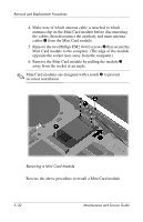
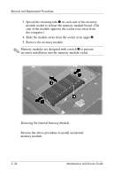
3. Spread the retaining tabs
1
on each side of the memory
module socket to release the memory module board. (The
side of the module opposite the socket rises away from
the computer.)
4. Slide the module away from the socket at an angle
2
.
5. Remove the memory module.
✎
Memory modules are designed with a notch
3
to prevent
incorrect installation into the memory module socket.
Removing the Internal Memory Module
Reverse the above procedure to install an internal
memory module.