HP Nx7400 HP Compaq nx7300 and nx7400 Notebook PC Maintenance and Service Guid - Page 129
Switch Cover, Switch Cover Spare Part Number Information
 |
UPC - 882780786653
View all HP Nx7400 manuals
Add to My Manuals
Save this manual to your list of manuals |
Page 129 highlights
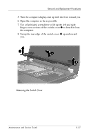
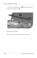
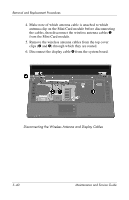
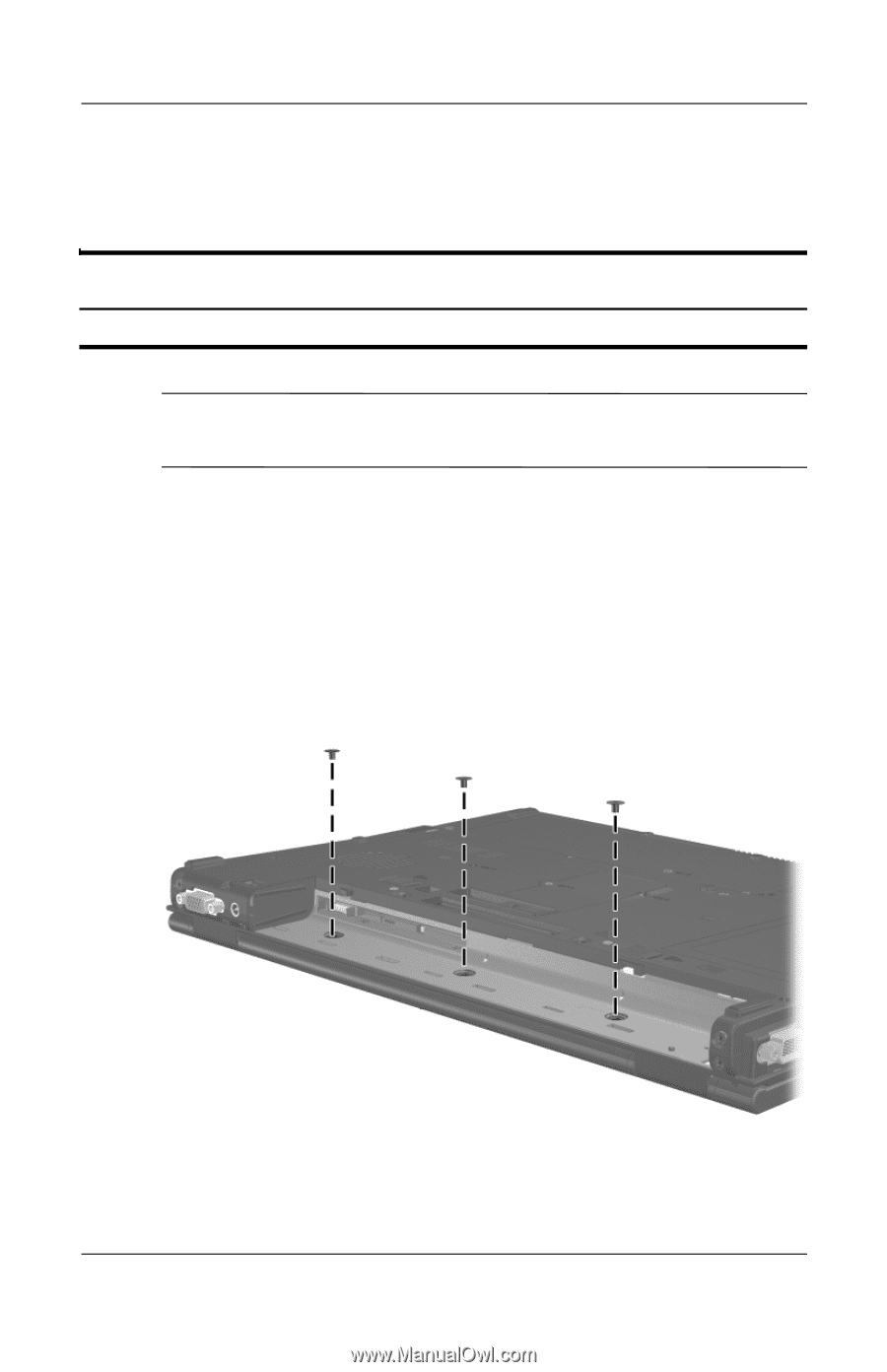
Removal and Replacement Procedures 5.17 Switch Cover Switch Cover Spare Part Number Information Switch cover (includes LED board and LED board cable) 417520-001 ✎ Both switch cover spare part kits include the LED board and LED board cable. 1. Prepare the computer for disassembly (Section 5.3). 2. Remove the keyboard (Section 5.9). 3. Turn the computer upside down with the rear panel toward you. 4. Remove the three Phillips PM2.0×2.0 screws that secure the switch cover to the computer. Removing the Switch Cover Screws 5-36 Maintenance and Service Guide
-
 1
1 -
2
-
3
-
4
-
5
-
6
-
7
-
8
-
9
-
10
-
11
-
12
-
13
-
14
-
15
-
16
-
17
-
18
-
19
-
20
-
21
-
22
-
23
-
24
-
25
-
26
-
27
-
28
-
29
-
30
-
31
-
32
-
33
-
34
-
35
-
36
-
37
-
38
-
39
-
40
-
41
-
42
-
43
-
44
-
45
-
46
-
47
-
48
-
49
-
50
-
51
-
52
-
53
-
54
-
55
-
56
-
57
-
58
-
59
-
60
-
61
-
62
-
63
-
64
-
65
-
66
-
67
-
68
-
69
-
70
-
71
-
72
-
73
-
74
-
75
-
76
-
77
-
78
-
79
-
80
-
81
-
82
-
83
-
84
-
85
-
86
-
87
-
88
-
89
-
90
-
91
-
92
-
93
-
94
-
95
-
96
-
97
-
98
-
99
-
100
-
101
-
102
-
103
-
104
-
105
-
106
-
107
-
108
-
109
-
110
-
111
-
112
-
113
-
114
-
115
-
116
-
117
-
118
-
119
-
120
-
121
-
122
-
123
-
 124
124 -
 125
125 -
 126
126 -
 127
127 -
 128
128 -
 129
129 -
 130
130 -
 131
131 -
 132
132 -
 133
133 -
 134
134 -
135
-
136
-
137
-
138
-
139
-
140
-
141
-
142
-
143
-
144
-
145
-
146
-
147
-
148
-
149
-
150
-
151
-
152
-
153
-
154
-
155
-
156
-
157
-
158
-
159
-
160
-
161
-
162
-
163
-
164
-
165
-
166
-
167
-
168
-
169
-
170
-
171
-
172
-
173
-
174
-
175
-
176
-
177
-
178
-
179
-
180
-
181
-
182
-
183
-
184
-
185
-
186
-
187
-
188
-
189
-
190
-
191
-
192
-
193
-
194
-
195
-
196
-
197
-
198
-
199
-
200
-
201
-
202
-
203
-
204
-
205
-
206
-
207
-
208
-
209
-
210
-
211
-
212
-
213
-
214
-
215
-
216
-
217
-
218
-
219
-
220
-
221
-
222
-
223
-
224
-
225
-
226
-
227
-
228
-
229
-
230
-
231
-
232
-
233
-
234
-
235
-
236
-
237
-
238
-
239
-
240
-
241
-
242
 |
 |
5–36
Maintenance and Service Guide
Removal and Replacement Procedures
5.17
Switch Cover
✎
Both switch cover spare part kits include the LED board and
LED board cable.
1. Prepare the computer for disassembly (
Section 5.3
).
2. Remove the keyboard (
Section 5.9
).
3. Turn the computer upside down with the rear panel
toward you.
4. Remove the three Phillips PM2.0×2.0 screws that secure the
switch cover to the computer.
Removing the Switch Cover Screws
Switch Cover Spare Part Number Information
Switch cover (includes LED board and LED board cable)
417520-001