HP Nx7400 HP Compaq nx7300 and nx7400 Notebook PC Maintenance and Service Guid - Page 149
System Board Frame (full-featured models only), System Board Frame Spare Part Number Information
 |
UPC - 882780786653
View all HP Nx7400 manuals
Add to My Manuals
Save this manual to your list of manuals |
Page 149 highlights
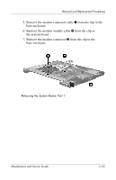
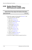
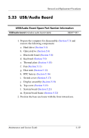
Removal and Replacement Procedures 5.22 System Board Frame (full-featured models only) System Board Frame Spare Part Number Information System board frame 416407-001 1. Prepare the computer for disassembly (Section 5.3) and remove the following components: a. Hard drive (Section 5.4) b. Optical drive (Section 5.6) c. Bluetooth module (Section 5.8) d. Keyboard (Section 5.9) e. Thermal plate(Section 5.10) f. Fan assembly (Section 5.11) g. Heat sink (Section 5.12) h. RTC battery (Section 5.16) i. Switch cover (Section 5.17) j. Top cover (Section 5.19) k. Display assembly (Section 5.18) l. System board (Section 5.21) 2. Position the computer with the rear panel toward you. 5-56 Maintenance and Service Guide
-
 1
1 -
2
-
3
-
4
-
5
-
6
-
7
-
8
-
9
-
10
-
11
-
12
-
13
-
14
-
15
-
16
-
17
-
18
-
19
-
20
-
21
-
22
-
23
-
24
-
25
-
26
-
27
-
28
-
29
-
30
-
31
-
32
-
33
-
34
-
35
-
36
-
37
-
38
-
39
-
40
-
41
-
42
-
43
-
44
-
45
-
46
-
47
-
48
-
49
-
50
-
51
-
52
-
53
-
54
-
55
-
56
-
57
-
58
-
59
-
60
-
61
-
62
-
63
-
64
-
65
-
66
-
67
-
68
-
69
-
70
-
71
-
72
-
73
-
74
-
75
-
76
-
77
-
78
-
79
-
80
-
81
-
82
-
83
-
84
-
85
-
86
-
87
-
88
-
89
-
90
-
91
-
92
-
93
-
94
-
95
-
96
-
97
-
98
-
99
-
100
-
101
-
102
-
103
-
104
-
105
-
106
-
107
-
108
-
109
-
110
-
111
-
112
-
113
-
114
-
115
-
116
-
117
-
118
-
119
-
120
-
121
-
122
-
123
-
124
-
125
-
126
-
127
-
128
-
129
-
130
-
131
-
132
-
133
-
134
-
135
-
136
-
137
-
138
-
139
-
140
-
141
-
142
-
143
-
 144
144 -
 145
145 -
 146
146 -
 147
147 -
 148
148 -
 149
149 -
 150
150 -
 151
151 -
 152
152 -
 153
153 -
 154
154 -
155
-
156
-
157
-
158
-
159
-
160
-
161
-
162
-
163
-
164
-
165
-
166
-
167
-
168
-
169
-
170
-
171
-
172
-
173
-
174
-
175
-
176
-
177
-
178
-
179
-
180
-
181
-
182
-
183
-
184
-
185
-
186
-
187
-
188
-
189
-
190
-
191
-
192
-
193
-
194
-
195
-
196
-
197
-
198
-
199
-
200
-
201
-
202
-
203
-
204
-
205
-
206
-
207
-
208
-
209
-
210
-
211
-
212
-
213
-
214
-
215
-
216
-
217
-
218
-
219
-
220
-
221
-
222
-
223
-
224
-
225
-
226
-
227
-
228
-
229
-
230
-
231
-
232
-
233
-
234
-
235
-
236
-
237
-
238
-
239
-
240
-
241
-
242
 |
 |
5–56
Maintenance and Service Guide
Removal and Replacement Procedures
5.22
System Board Frame
(full-featured models only)
1. Prepare the computer for disassembly (
Section 5.3
) and
remove the following components:
a.
Hard drive (
Section 5.4
)
b.
Optical drive (
Section 5.6
)
c.
Bluetooth module (
Section 5.8
)
d.
Keyboard (
Section 5.9
)
e.
Thermal plate(
Section 5.10
)
f.
Fan assembly (
Section 5.11
)
g.
Heat sink (
Section 5.12
)
h.
RTC battery (
Section 5.16
)
i.
Switch cover (
Section 5.17
)
j.
Top cover (
Section 5.19
)
k.
Display assembly (
Section 5.18
)
l.
System board (
Section 5.21
)
2. Position the computer with the rear panel toward you.
System Board Frame Spare Part Number Information
System board frame
416407-001