HP Pavilion TouchSmart 14-n028ca HP Pavilion 14 Notebook PC HP Pavilion TouchS - Page 76
Power button board
 |
View all HP Pavilion TouchSmart 14-n028ca manuals
Add to My Manuals
Save this manual to your list of manuals |
Page 76 highlights
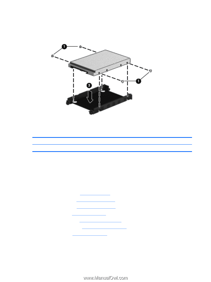
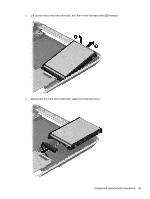
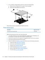
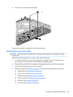
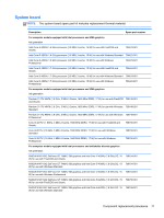
4. If it is necessary to disassemble the hard drive, perform the following steps: a. Remove the four Phillips M3.0×3.5 screws (1) from the bracket. b. Remove the bracket (2) from the hard drive. Reverse this procedure to reassemble and install the hard drive. Power button board Description Power button board (includes cable) Spare part number 734416-001 Before removing the power button board, follow these steps: 1. Turn off the computer. If you are unsure whether the computer is off or in Hibernation, turn the computer on, and then shut it down through the operating system. 2. Disconnect the power from the computer by unplugging the power cord from the computer. 3. Disconnect all external devices from the computer. 4. Remove the battery (see Battery on page 42), and then remove the following components: a. Optical drive (see Optical drive on page 48) b. Service door (see Service door on page 43) c. Keyboard (see Keyboard on page 54) d. WLAN module (see WLAN module on page 46) e. Memory module (see Memory module on page 44) f. Top cover (see Top cover on page 59) 66 Chapter 6 Removal and replacement procedures for Authorized Service Provider parts
-
 1
1 -
2
-
3
-
4
-
5
-
6
-
7
-
8
-
9
-
10
-
11
-
12
-
13
-
14
-
15
-
16
-
17
-
18
-
19
-
20
-
21
-
22
-
23
-
24
-
25
-
26
-
27
-
28
-
29
-
30
-
31
-
32
-
33
-
34
-
35
-
36
-
37
-
38
-
39
-
40
-
41
-
42
-
43
-
44
-
45
-
46
-
47
-
48
-
49
-
50
-
51
-
52
-
53
-
54
-
55
-
56
-
57
-
58
-
59
-
60
-
61
-
62
-
63
-
64
-
65
-
66
-
67
-
68
-
69
-
70
-
 71
71 -
 72
72 -
 73
73 -
 74
74 -
 75
75 -
 76
76 -
 77
77 -
 78
78 -
 79
79 -
 80
80 -
 81
81 -
82
-
83
-
84
-
85
-
86
-
87
-
88
-
89
-
90
-
91
-
92
-
93
-
94
-
95
-
96
-
97
-
98
-
99
-
100
-
101
-
102
-
103
-
104
-
105
-
106
-
107
-
108
-
109
-
110
-
111
-
112
-
113
-
114
-
115
-
116
-
117
-
118
-
119
-
120
-
121
-
122
-
123
-
124
-
125
-
126
-
127
-
128
-
129
-
130
 |
 |