HP Pavilion dv6-3300 HP Pavilion dv6 Entertainment PC - Maintenance and Servic - Page 105
Fan/heat sink assembly, computer on, and then shut it down through the operating system.
 |
View all HP Pavilion dv6-3300 manuals
Add to My Manuals
Save this manual to your list of manuals |
Page 105 highlights
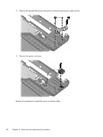
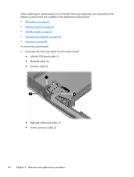
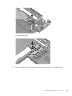
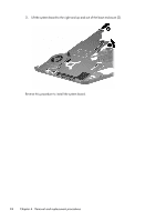
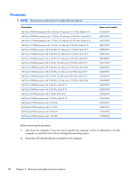
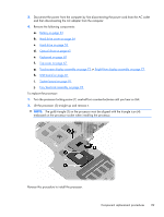
Fan/heat sink assembly NOTE: The fan/heat sink assembly spare kit includes replacement thermal material. Description For use only with computer models equipped with UMA graphics memory For use only with computer models equipped with UMA graphics memory and a processor For use only with computer models equipped with discrete graphics memory and a 45 W processor For use only with computer models equipped with discrete graphics memory and a 35 W processor Spare part number 603690-001 633384-001 604787-001 603691-001 NOTE: To properly ventilate the computer, allow at least a 7.6-cm (3-inch) clearance on the right side and rear panel of the computer. The computer uses an electric fan for ventilation. The fan is controlled by a temperature sensor and is designed to turn on automatically when high temperature conditions exist. These conditions are affected by high external temperatures, system power consumption, power management/battery conservation configurations, battery fast charging, and software requirements. Exhaust air is displaced through the ventilation grill located on the left side of the computer. Before removing the fan/heat sink assembly: 1. Shut down the computer. If you are unsure whether the computer is off or in Hibernation, turn the computer on, and then shut it down through the operating system. 2. Disconnect all external devices connected to the computer. 3. Disconnect the power from the computer by first disconnecting the power cord from the AC outlet and then disconnecting the AC adapter from the computer. 4. Remove the following components: a. Battery on page 53 b. Hard drive cover on page 54 c. Hard drive on page 55 d. Optical drive on page 63 e. Keyboard on page 65 f. Top cover on page 67 g. Touchscreen display assembly on page 72 or BrightView display assembly on page 77 h. USB board on page 87 i. System board on page 91 Component replacement procedures 95
-
 1
1 -
2
-
3
-
4
-
5
-
6
-
7
-
8
-
9
-
10
-
11
-
12
-
13
-
14
-
15
-
16
-
17
-
18
-
19
-
20
-
21
-
22
-
23
-
24
-
25
-
26
-
27
-
28
-
29
-
30
-
31
-
32
-
33
-
34
-
35
-
36
-
37
-
38
-
39
-
40
-
41
-
42
-
43
-
44
-
45
-
46
-
47
-
48
-
49
-
50
-
51
-
52
-
53
-
54
-
55
-
56
-
57
-
58
-
59
-
60
-
61
-
62
-
63
-
64
-
65
-
66
-
67
-
68
-
69
-
70
-
71
-
72
-
73
-
74
-
75
-
76
-
77
-
78
-
79
-
80
-
81
-
82
-
83
-
84
-
85
-
86
-
87
-
88
-
89
-
90
-
91
-
92
-
93
-
94
-
95
-
96
-
97
-
98
-
99
-
 100
100 -
 101
101 -
 102
102 -
 103
103 -
 104
104 -
 105
105 -
 106
106 -
 107
107 -
 108
108 -
 109
109 -
 110
110 -
111
-
112
-
113
-
114
-
115
-
116
-
117
-
118
-
119
-
120
-
121
-
122
-
123
-
124
-
125
-
126
-
127
-
128
-
129
-
130
-
131
-
132
-
133
-
134
-
135
-
136
-
137
-
138
-
139
-
140
-
141
-
142
-
143
-
144
-
145
-
146
-
147
-
148
-
149
-
150
-
151
-
152
-
153
-
154
-
155
 |
 |