HP Pavilion dv6-3300 HP Pavilion dv6 Entertainment PC - Maintenance and Servic - Page 88
Keyboard, on Top cover
 |
View all HP Pavilion dv6-3300 manuals
Add to My Manuals
Save this manual to your list of manuals |
Page 88 highlights
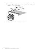
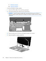
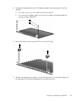
f. Keyboard on page 65 g. Top cover on page 67 To remove the BrightView display assembly: 1. Remove the WLAN cables (1) from under the system board. 2. Disconnect the display panel cable (2) from the system board. CAUTION: Support the display assembly when removing the following screws. Failure to support the display assembly might result in damage to the display assembly and other computer components. 3. Remove the three screws (1) that secure the display assembly to the computer. 4. Remove the BrightView display assembly (2). 78 Chapter 4 Removal and replacement procedures
-
 1
1 -
2
-
3
-
4
-
5
-
6
-
7
-
8
-
9
-
10
-
11
-
12
-
13
-
14
-
15
-
16
-
17
-
18
-
19
-
20
-
21
-
22
-
23
-
24
-
25
-
26
-
27
-
28
-
29
-
30
-
31
-
32
-
33
-
34
-
35
-
36
-
37
-
38
-
39
-
40
-
41
-
42
-
43
-
44
-
45
-
46
-
47
-
48
-
49
-
50
-
51
-
52
-
53
-
54
-
55
-
56
-
57
-
58
-
59
-
60
-
61
-
62
-
63
-
64
-
65
-
66
-
67
-
68
-
69
-
70
-
71
-
72
-
73
-
74
-
75
-
76
-
77
-
78
-
79
-
80
-
81
-
82
-
 83
83 -
 84
84 -
 85
85 -
 86
86 -
 87
87 -
 88
88 -
 89
89 -
 90
90 -
 91
91 -
 92
92 -
 93
93 -
94
-
95
-
96
-
97
-
98
-
99
-
100
-
101
-
102
-
103
-
104
-
105
-
106
-
107
-
108
-
109
-
110
-
111
-
112
-
113
-
114
-
115
-
116
-
117
-
118
-
119
-
120
-
121
-
122
-
123
-
124
-
125
-
126
-
127
-
128
-
129
-
130
-
131
-
132
-
133
-
134
-
135
-
136
-
137
-
138
-
139
-
140
-
141
-
142
-
143
-
144
-
145
-
146
-
147
-
148
-
149
-
150
-
151
-
152
-
153
-
154
-
155
 |
 |
f.
Keyboard
on page
65
g.
Top cover
on page
67
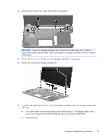
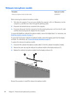
To remove the BrightView display assembly:
1.
Remove the WLAN cables (1) from under the system board.
2.
Disconnect the display panel cable (2) from the system board.
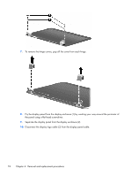
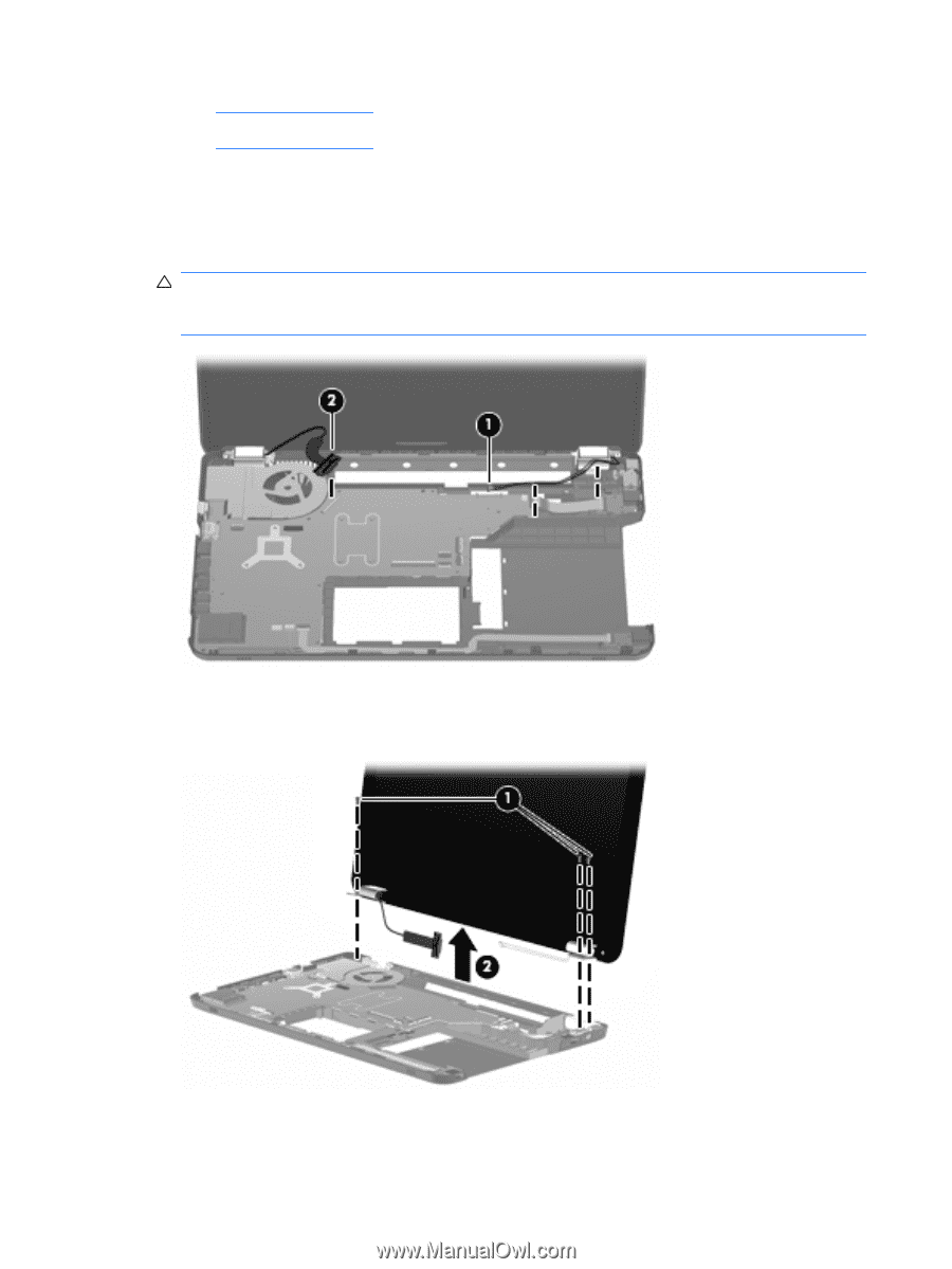
CAUTION:
Support the display assembly when removing the following screws. Failure to
support the display assembly might result in damage to the display assembly and other computer
components.
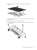
3.
Remove the three screws (1) that secure the display assembly to the computer.
4.
Remove the BrightView display assembly (2).
78
Chapter 4
Removal and replacement procedures