HP Pavilion dv6-3300 HP Pavilion dv6 Entertainment PC - Maintenance and Servic - Page 83
CAUTION, Two rubber screw covers on the display bezel bottom edge 1. The display rubber screw
 |
View all HP Pavilion dv6-3300 manuals
Add to My Manuals
Save this manual to your list of manuals |
Page 83 highlights
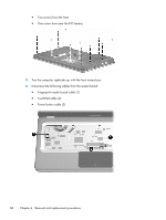
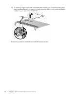
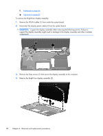
3. Disconnect the touchscreen cable (3) from the system board. CAUTION: Support the display assembly when removing the following screws. Failure to support the display assembly might result in damage to the display assembly and other computer components. 4. Remove the three screws (1) that secure the display assembly to the computer. 5. Remove the Touchscreen display assembly (2). 6. To replace the display enclosure or any of the display assembly internal components, remove the following: ● Two rubber screw covers on the display bezel bottom edge (1). The display rubber screw covers are included in the Display Rubber Kit, spare part number 603659-001. ● Two screws (2). Component replacement procedures 73
-
 1
1 -
2
-
3
-
4
-
5
-
6
-
7
-
8
-
9
-
10
-
11
-
12
-
13
-
14
-
15
-
16
-
17
-
18
-
19
-
20
-
21
-
22
-
23
-
24
-
25
-
26
-
27
-
28
-
29
-
30
-
31
-
32
-
33
-
34
-
35
-
36
-
37
-
38
-
39
-
40
-
41
-
42
-
43
-
44
-
45
-
46
-
47
-
48
-
49
-
50
-
51
-
52
-
53
-
54
-
55
-
56
-
57
-
58
-
59
-
60
-
61
-
62
-
63
-
64
-
65
-
66
-
67
-
68
-
69
-
70
-
71
-
72
-
73
-
74
-
75
-
76
-
77
-
 78
78 -
 79
79 -
 80
80 -
 81
81 -
 82
82 -
 83
83 -
 84
84 -
 85
85 -
 86
86 -
 87
87 -
 88
88 -
89
-
90
-
91
-
92
-
93
-
94
-
95
-
96
-
97
-
98
-
99
-
100
-
101
-
102
-
103
-
104
-
105
-
106
-
107
-
108
-
109
-
110
-
111
-
112
-
113
-
114
-
115
-
116
-
117
-
118
-
119
-
120
-
121
-
122
-
123
-
124
-
125
-
126
-
127
-
128
-
129
-
130
-
131
-
132
-
133
-
134
-
135
-
136
-
137
-
138
-
139
-
140
-
141
-
142
-
143
-
144
-
145
-
146
-
147
-
148
-
149
-
150
-
151
-
152
-
153
-
154
-
155
 |
 |
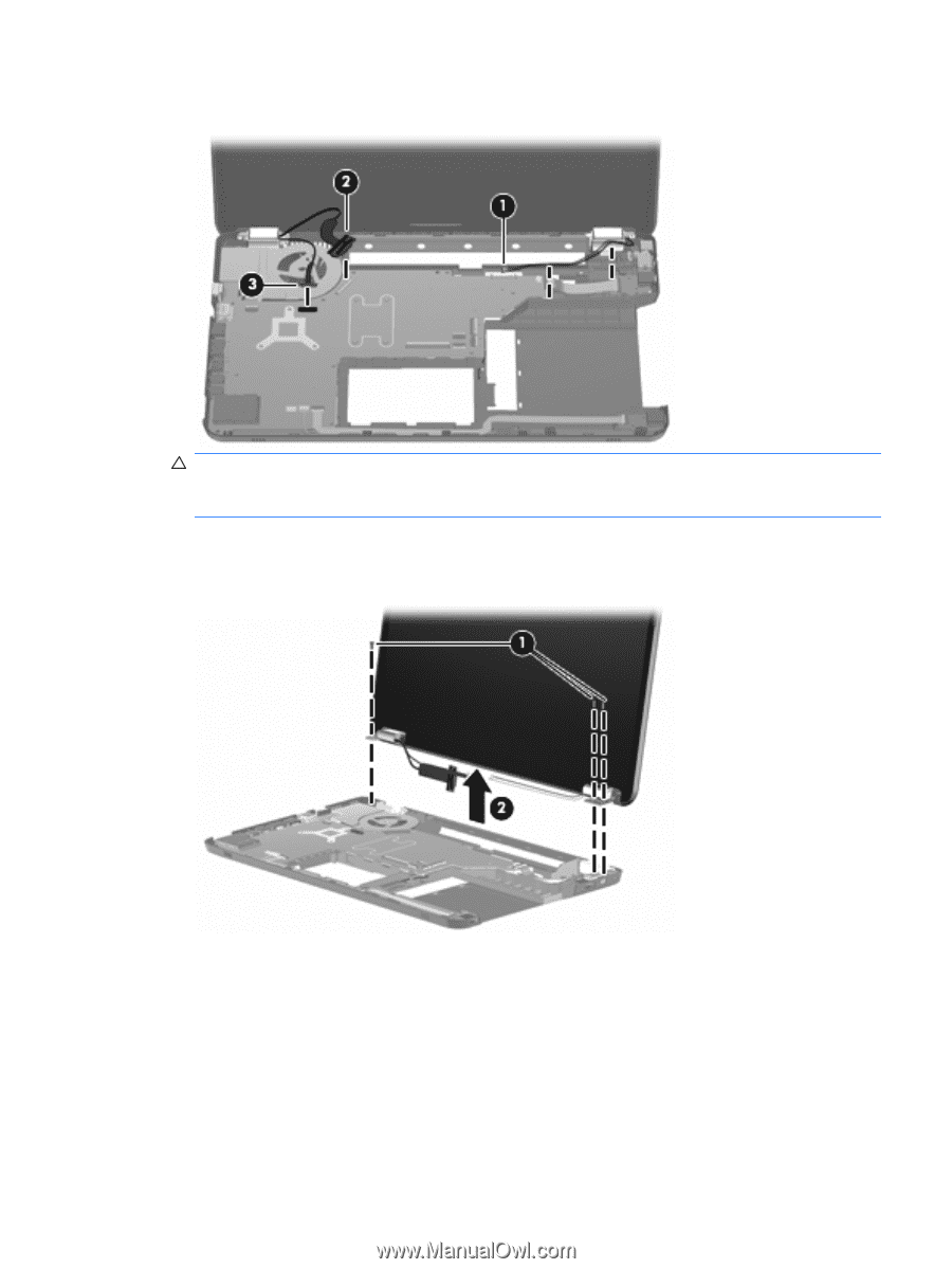
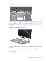
3.
Disconnect the touchscreen cable (3) from the system board.
CAUTION:
Support the display assembly when removing the following screws. Failure to
support the display assembly might result in damage to the display assembly and other computer
components.
4.
Remove the three screws (1) that secure the display assembly to the computer.
5.
Remove the Touchscreen display assembly (2).
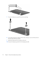
6.
To replace the display enclosure or any of the display assembly internal components, remove the
following:
●
Two rubber screw covers on the display bezel bottom edge (1). The display rubber screw
covers are included in the Display Rubber Kit, spare part number 603659-001.
●
Two screws (2).
Component replacement procedures
73