HP Pavilion dv6-3300 HP Pavilion dv6 Entertainment PC - Maintenance and Servic - Page 87
BrightView display assembly, Disconnect all external devices connected to the computer.
 |
View all HP Pavilion dv6-3300 manuals
Add to My Manuals
Save this manual to your list of manuals |
Page 87 highlights
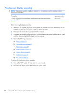
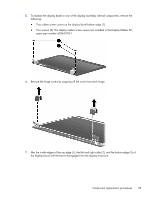
BrightView display assembly NOTE: The display assembly includes two wireless antenna transceivers and cables. Description 39.6-cm (15.6-inch) HD BrightView display assembly with low light VGA webcam and two microphones (Black) 39.6-cm (15.6-inch) HD BrightView display assembly with low light VGA webcam and two microphones (White) 39.6-cm (15.6-inch) HD BrightView display assembly with low light VGA webcam and two microphones (Red) 39.6-cm (15.6-inch) HD BrightView display assembly with low light VGA webcam and two microphones (Chrome) 39.6-cm (15.6-inch) HD BrightView display assembly with low light VGA webcam and two microphones (Midnight blue) 39.6-cm (15.6-inch) HD BrightView display assembly with low light VGA webcam and two microphones (Black) with WiMAX 39.6-cm (15.6-inch) HD BrightView display assembly with low light VGA webcam and two microphones (Etched) with WiMAX 39.6-cm (15.6-inch) HD BrightView display assembly with low light VGA webcam and two microphones (Rossignol Special Edition AT (Attraxion)) 39.6-cm (15.6-inch) HD BrightView display assembly with low light VGA webcam and two microphones (Rossignol Special Edition KP (Koopman)) 39.6-cm (15.6-inch) HD BrightView display assembly with low light VGA webcam and two microphones (Etched) Spare part number 603647-001 603648-001 603649-001 603650-001 615932-001 629279-001 629280-001 635372-001 635373-001 595131-001 Before removing the BrightView display assembly: 1. Shut down the computer. If you are unsure whether the computer is off or in Hibernation, turn the computer on, and then shut it down through the operating system. 2. Disconnect all external devices connected to the computer. 3. Disconnect the power from the computer by first disconnecting the power cord from the AC outlet and then disconnecting the AC adapter from the computer. 4. Remove the following components: a. Battery on page 53 b. Hard drive cover on page 54 c. Hard drive on page 55 d. WLAN module on page 57 e. Optical drive on page 63 Component replacement procedures 77
-
 1
1 -
2
-
3
-
4
-
5
-
6
-
7
-
8
-
9
-
10
-
11
-
12
-
13
-
14
-
15
-
16
-
17
-
18
-
19
-
20
-
21
-
22
-
23
-
24
-
25
-
26
-
27
-
28
-
29
-
30
-
31
-
32
-
33
-
34
-
35
-
36
-
37
-
38
-
39
-
40
-
41
-
42
-
43
-
44
-
45
-
46
-
47
-
48
-
49
-
50
-
51
-
52
-
53
-
54
-
55
-
56
-
57
-
58
-
59
-
60
-
61
-
62
-
63
-
64
-
65
-
66
-
67
-
68
-
69
-
70
-
71
-
72
-
73
-
74
-
75
-
76
-
77
-
78
-
79
-
80
-
81
-
 82
82 -
 83
83 -
 84
84 -
 85
85 -
 86
86 -
 87
87 -
 88
88 -
 89
89 -
 90
90 -
 91
91 -
 92
92 -
93
-
94
-
95
-
96
-
97
-
98
-
99
-
100
-
101
-
102
-
103
-
104
-
105
-
106
-
107
-
108
-
109
-
110
-
111
-
112
-
113
-
114
-
115
-
116
-
117
-
118
-
119
-
120
-
121
-
122
-
123
-
124
-
125
-
126
-
127
-
128
-
129
-
130
-
131
-
132
-
133
-
134
-
135
-
136
-
137
-
138
-
139
-
140
-
141
-
142
-
143
-
144
-
145
-
146
-
147
-
148
-
149
-
150
-
151
-
152
-
153
-
154
-
155
 |
 |