HP Pavilion dv7-4000 HP Pavilion dv7 Entertainment PC - Maintenance and Servic - Page 69
Top cover, Remove the top cover
 |
View all HP Pavilion dv7-4000 manuals
Add to My Manuals
Save this manual to your list of manuals |
Page 69 highlights
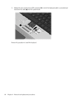
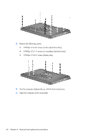
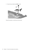
Top cover Description Top cover (includes TouchPad and TouchPad buttons) for use only with silver computer models equipped with a fingerprint reader; and includes fingerprint reader board Top cover (includes TouchPad and TouchPad buttons) for use only with black computer models not equipped with a fingerprint reader Top cover (includes TouchPad and TouchPad buttons) for use only with white computer models not equipped with a fingerprint reader Spare part number 605346-001 605347-001 609789-001 Before removing the top cover, follow these steps: 1. Shut down the computer. If you are unsure whether the computer is off or in Hibernation, turn the computer on, and then shut it down through the operating system. 2. Disconnect all external devices connected to the computer. 3. Disconnect the power from the computer by first unplugging the power cord from the AC outlet and then unplugging the AC adapter from the computer. 4. Remove the battery (see Battery on page 46). 5. Remove the primary hard drive cover (see Primary hard drive cover on page 47). 6. Remove the hard drive (see Hard drive on page 48). 7. Remove the secondary hard drive (see Secondary hard drive on page 50). 8. Remove the optical drive (see Optical drive on page 57). 9. Remove the keyboard (see Keyboard on page 58). Remove the top cover: 1. Turn the computer display-side down, with the front toward you. 2. Remove the following screws: ● 4 Phillips 2.5×6.5 screws (one in each corner) ● 2 Phillips 2.5×6.5 screws (left side) ● 2 Phillips 2.5×6.5 screws (front side) ● 1 Phillips 2.5×6.5 screws (center) ● 5 Phillips 2.0×1.5 screws (in battery bay) Component replacement procedures 61
-
 1
1 -
2
-
3
-
4
-
5
-
6
-
7
-
8
-
9
-
10
-
11
-
12
-
13
-
14
-
15
-
16
-
17
-
18
-
19
-
20
-
21
-
22
-
23
-
24
-
25
-
26
-
27
-
28
-
29
-
30
-
31
-
32
-
33
-
34
-
35
-
36
-
37
-
38
-
39
-
40
-
41
-
42
-
43
-
44
-
45
-
46
-
47
-
48
-
49
-
50
-
51
-
52
-
53
-
54
-
55
-
56
-
57
-
58
-
59
-
60
-
61
-
62
-
63
-
 64
64 -
 65
65 -
 66
66 -
 67
67 -
 68
68 -
 69
69 -
 70
70 -
 71
71 -
 72
72 -
 73
73 -
 74
74 -
75
-
76
-
77
-
78
-
79
-
80
-
81
-
82
-
83
-
84
-
85
-
86
-
87
-
88
-
89
-
90
-
91
-
92
-
93
-
94
-
95
-
96
-
97
-
98
-
99
-
100
-
101
-
102
-
103
-
104
-
105
-
106
-
107
-
108
-
109
-
110
-
111
-
112
-
113
-
114
-
115
-
116
-
117
-
118
-
119
-
120
-
121
-
122
-
123
-
124
-
125
-
126
-
127
-
128
-
129
-
130
-
131
-
132
-
133
-
134
-
135
-
136
-
137
-
138
-
139
-
140
-
141
 |
 |