HP Pavilion dv7-4000 HP Pavilion dv7 Entertainment PC - Maintenance and Servic - Page 77
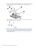
Two Phillips PM2.5×7.0 screws., components, remove the following screw covers and screws
 |
View all HP Pavilion dv7-4000 manuals
Add to My Manuals
Save this manual to your list of manuals |
Page 77 highlights
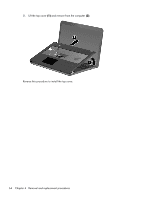
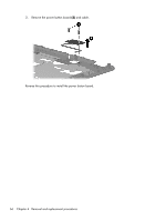
3. Remove the display assembly (2). NOTE: Steps 4 through 17 provide display assembly internal component removal information for computer models equipped with flush glass display assemblies. See steps 18 through 29 for display assembly internal component removal information for computer models equipped with BrightView display assemblies. 4. If it is necessary to replace the display enclosure or any of the display assembly internal components, remove the following screw covers and screws: (1) Two rubber screw covers on the display bezel bottom edge. The rubber screw covers are included in the Display Rubber Kit, spare part number 605341-001. (2) Two Phillips PM2.5×7.0 screws. Component replacement procedures 69
-
 1
1 -
2
-
3
-
4
-
5
-
6
-
7
-
8
-
9
-
10
-
11
-
12
-
13
-
14
-
15
-
16
-
17
-
18
-
19
-
20
-
21
-
22
-
23
-
24
-
25
-
26
-
27
-
28
-
29
-
30
-
31
-
32
-
33
-
34
-
35
-
36
-
37
-
38
-
39
-
40
-
41
-
42
-
43
-
44
-
45
-
46
-
47
-
48
-
49
-
50
-
51
-
52
-
53
-
54
-
55
-
56
-
57
-
58
-
59
-
60
-
61
-
62
-
63
-
64
-
65
-
66
-
67
-
68
-
69
-
70
-
71
-
 72
72 -
 73
73 -
 74
74 -
 75
75 -
 76
76 -
 77
77 -
 78
78 -
 79
79 -
 80
80 -
 81
81 -
 82
82 -
83
-
84
-
85
-
86
-
87
-
88
-
89
-
90
-
91
-
92
-
93
-
94
-
95
-
96
-
97
-
98
-
99
-
100
-
101
-
102
-
103
-
104
-
105
-
106
-
107
-
108
-
109
-
110
-
111
-
112
-
113
-
114
-
115
-
116
-
117
-
118
-
119
-
120
-
121
-
122
-
123
-
124
-
125
-
126
-
127
-
128
-
129
-
130
-
131
-
132
-
133
-
134
-
135
-
136
-
137
-
138
-
139
-
140
-
141
 |
 |
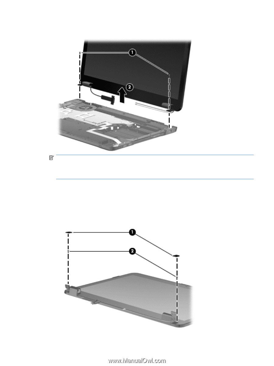
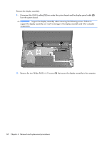
3.
Remove the display assembly
(2)
.
NOTE:
Steps 4 through 17 provide display assembly internal component removal information
for computer models equipped with flush glass display assemblies. See steps 18 through 29 for
display assembly internal component removal information for computer models equipped with
BrightView display assemblies.
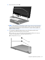
4.
If it is necessary to replace the display enclosure or any of the display assembly internal
components, remove the following screw covers and screws:
(1)
Two rubber screw covers on the display bezel bottom edge. The rubber screw covers are
included in the Display Rubber Kit, spare part number 605341-001.
(2)
Two Phillips PM2.5×7.0 screws.
Component replacement procedures
69