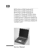
HP Pavilion xt500 HP Pavilion & Compaq Presario Notebook PC - Service Manu - Page 4
s, Replaceable Parts, Reference Information
 |
View all HP Pavilion xt500 manuals
Add to My Manuals
Save this manual to your list of manuals |
Page 4 highlights
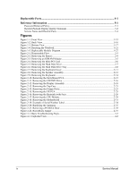
Replaceable Parts...4-1 Reference Information 5-1 Password Removal Policy...5-1 Hewlett-Packard Display Quality Statement 5-2 Service Notes and Obsolete Parts 5-4 Figures Figure 1-1. Front View ...1-15 Figure 1-2. Back View...1-16 Figure 1-3. Bottom View ...1-17 Figure 1-4. Resetting the Notebook 1-21 Figure 1-5. Replaceable Module Diagram 1-27 Figure 2-1. Disassembly Flow ...2-3 Figure 2-2. Removing the Battery ...2-4 Figure 2-3. Removing an SDRAM Module 2-5 Figure 2-4. Removing the Mini-PCI Card 2-6 Figure 2-5. Removing the Hard Disk Drive 2-7 Figure 2-6. Removing the Hard Disk Drive Tray 2-8 Figure 2-7. Removing the Keyboard Cover 2-11 Figure 2-8. Removing the Speaker Assembly 2-12 Figure 2-9. Removing the Keyboard 2-14 Figure 2-10. Removing the Switchboard PCA 2-15 Figure 2-11. Removing the CD/DVD Drive 2-16 Figure 2-12. Removing the Display Assembly 2-18 Figure 2-13. Removing the Top Case 2-21 Figure 2-14. Removing the Floppy Drive 2-23 Figure 2-15. Removing the I/R PCA 2-25 Figure 2-16. Removing the Heatsink (with Fan 2-26 Figure 2-17. Removing the CPU Module 2-29 Figure 2-18. Removing the Motherboard 2-31 Figure 2-19. Example of Serial Number Label 2-34 Figure 2-20. Replacing the Antennas 2-35 Figure 2-21. Removing a PCMCIA Door 2-35 Figure 2-22. Boot-Block Jumper ...2-37 Figure 3-1. Basic Troubleshooting Steps 3-2 Figure 4-1. Exploded View...4-2 iv Service Manual
-
 1
1 -
 2
2 -
 3
3 -
 4
4 -
 5
5 -
 6
6 -
 7
7 -
 8
8 -
 9
9 -
 10
10 -
11
-
12
-
13
-
14
-
15
-
16
-
17
-
18
-
19
-
20
-
21
-
22
-
23
-
24
-
25
-
26
-
27
-
28
-
29
-
30
-
31
-
32
-
33
-
34
-
35
-
36
-
37
-
38
-
39
-
40
-
41
-
42
-
43
-
44
-
45
-
46
-
47
-
48
-
49
-
50
-
51
-
52
-
53
-
54
-
55
-
56
-
57
-
58
-
59
-
60
-
61
-
62
-
63
-
64
-
65
-
66
-
67
-
68
-
69
-
70
-
71
-
72
-
73
-
74
-
75
-
76
-
77
-
78
-
79
-
80
-
81
-
82
-
83
-
84
-
85
-
86
-
87
-
88
-
89
-
90
-
91
-
92
-
93
-
94
-
95
-
96
-
97
-
98
-
99
-
100
-
101
-
102
-
103
-
104
-
105
-
106
-
107
-
108
-
109
-
110
-
111
-
112
-
113
-
114
-
115
-
116
-
117
-
118
-
119
-
120
-
121
-
122
-
123
-
124
-
125
-
126
 |
 |
