HP ProLiant SL390s HP ProLiant SL390s G7 2U half width Server Maintenance and - Page 38
System Board Configuration, Processor
 |
View all HP ProLiant SL390s manuals
Add to My Manuals
Save this manual to your list of manuals |
Page 38 highlights
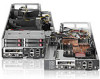
Figure 12 Removing the backplane To install the backplane: 1. Make the screw holes on the backplane align with the holes on the hard drive cage. 2. Secure the backplane with two screws. 3. Install all cables. Figure 13 Installing the HDD backplane System Board Configuration Processor HP ProLiant SL390s G7 2U Server, with 4 Nodes, supports eight -processor operation. With two processors installed, each Node supports boot functions through the processor installed in processor Removal and Replacement Procedures 38
-
 1
1 -
2
-
3
-
4
-
5
-
6
-
7
-
8
-
9
-
10
-
11
-
12
-
13
-
14
-
15
-
16
-
17
-
18
-
19
-
20
-
21
-
22
-
23
-
24
-
25
-
26
-
27
-
28
-
29
-
30
-
31
-
32
-
 33
33 -
 34
34 -
 35
35 -
 36
36 -
 37
37 -
 38
38 -
 39
39 -
 40
40 -
 41
41 -
 42
42 -
 43
43 -
44
-
45
-
46
-
47
-
48
-
49
-
50
-
51
-
52
-
53
-
54
-
55
-
56
-
57
-
58
-
59
-
60
-
61
-
62
-
63
-
64
-
65
-
66
-
67
-
68
-
69
-
70
-
71
-
72
-
73
-
74
-
75
-
76
-
77
-
78
-
79
-
80
-
81
-
82
-
83
-
84
 |
 |

Removal and Replacement Procedures 38
Figure 12
Removing the backplane
To install the backplane:
1.
Make the screw holes on the backplane align with the holes on the hard drive cage.
2.
Secure the backplane with two screws.
3.
Install all cables.
Figure 13
Installing the
HDD backplane
System Board Configuration
Processor
HP ProLiant SL390s G7 2U Server, with 4 Nodes, supports eight -processor operation. With two
processors installed, each Node supports boot functions through the processor installed in processor