HP ProLiant SL390s HP ProLiant SL390s G7 2U half width Server Maintenance and - Page 39
W, 95W, 80W Dual CPUs 64-bit, and Nehalem Processors Low Wattage 60W and Westmere
 |
View all HP ProLiant SL390s manuals
Add to My Manuals
Save this manual to your list of manuals |
Page 39 highlights
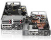
socket 1. However, if processor 1 fails, the system automatically boots from processor 2 and provides a processor failure message. The processor socket supports Quad-Core Intel Nehalem and Westmere Processors High Wattage 130W,95W,80W (Dual CPUs 64-bit), and Nehalem Processors Low Wattage 60W and Westmere Processor Low Wattage 40W(Dual CPUs 64-bit). CAUTION: It is recommended to use processors of the same speeds or cache sizes to prevent possible server malfunction. Figure 14 Processor locations Item Description 1 Processor 1 2 Processor 2 WARNING: To reduce the risk of personal injury from hot surfaces, allow the heat sink and the processor to cool before touching them. To remove the heat sink: CAUTION: To prevent the heat sink from tilting to one side during installation and removal procedures, use a diagonally opposite pattern (an "X" pattern) when loosening and tightening the two spring-loaded screws. Do not over tighten the heat sink's spring-loaded screws to prevent them from breaking off. A maximum torque of 4 in-Ib is set for the system. 1. Loosen the two mounting pins. 2. Lift the heat sink away from the system board. CAUTION: Place the heat sink down in an upright position with the thermal patch facing upward. Do not let the thermal patch touch the work surface. Removal and Replacement Procedures 39
-
 1
1 -
2
-
3
-
4
-
5
-
6
-
7
-
8
-
9
-
10
-
11
-
12
-
13
-
14
-
15
-
16
-
17
-
18
-
19
-
20
-
21
-
22
-
23
-
24
-
25
-
26
-
27
-
28
-
29
-
30
-
31
-
32
-
33
-
 34
34 -
 35
35 -
 36
36 -
 37
37 -
 38
38 -
 39
39 -
 40
40 -
 41
41 -
 42
42 -
 43
43 -
 44
44 -
45
-
46
-
47
-
48
-
49
-
50
-
51
-
52
-
53
-
54
-
55
-
56
-
57
-
58
-
59
-
60
-
61
-
62
-
63
-
64
-
65
-
66
-
67
-
68
-
69
-
70
-
71
-
72
-
73
-
74
-
75
-
76
-
77
-
78
-
79
-
80
-
81
-
82
-
83
-
84
 |
 |
