HP SignagePlayer mp8000r Maintenance & Service Guide: HP SignagePlayer mp8
HP SignagePlayer mp8000r Manual
 |
View all HP SignagePlayer mp8000r manuals
Add to My Manuals
Save this manual to your list of manuals |
HP SignagePlayer mp8000r manual content summary:
- HP SignagePlayer mp8000r | Maintenance & Service Guide: HP SignagePlayer mp8 - Page 1
Maintenance and Service Guide HP SignagePlayer mp8000r and mp8000s - HP SignagePlayer mp8000r | Maintenance & Service Guide: HP SignagePlayer mp8 - Page 2
HP products and services are set forth in the express warranty statements accompanying such products and services. Nothing herein should be construed as constituting an additional warranty. HP Hewlett-Packard Company. HP SignagePlayer mp8000r and mp8000s First Edition (December 2010) Document Part - HP SignagePlayer mp8000r | Maintenance & Service Guide: HP SignagePlayer mp8 - Page 3
About This Book WARNING! Text set off in this manner indicates that failure to follow directions could result in bodily harm or loss of life. CAUTION: Text set off in this manner indicates that failure to follow directions could result in damage to equipment or loss of information. NOTE: Text set - HP SignagePlayer mp8000r | Maintenance & Service Guide: HP SignagePlayer mp8 - Page 4
iv About This Book - HP SignagePlayer mp8000r | Maintenance & Service Guide: HP SignagePlayer mp8 - Page 5
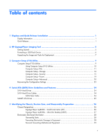
and Quick Release Installation 1 Display Information ...1 Quick Release ...1 2 HP SignagePlayer Imaging Tool 5 Getting Started ...5 Formatting a USB Flash Device 6 26 Chassis Designations ...26 Signage Player mp8000r - Small Form Factor (SFF 26 Signage Player mp8000s - Ultra-Slim Desktop - HP SignagePlayer mp8000r | Maintenance & Service Guide: HP SignagePlayer mp8 - Page 6
the Keyboard 31 Cleaning the Monitor 32 Cleaning the Mouse 32 Service Considerations ...32 Power Supply Fan 32 Tools and Software Requirements Devices ...38 Installing a Security Lock 38 HP/Kensington MicroSaver Security Cable Lock 38 Padlock 39 HP Business PC Security Lock 39 Front Bezel - HP SignagePlayer mp8000r | Maintenance & Service Guide: HP SignagePlayer mp8 - Page 7
-Slim Desktop (USDT) Chassis 92 Preparation for Disassembly ...92 Security Lock Provisions ...93 Installing a Security Lock 93 HP/Kensington MicroSaver Security Cable Lock 93 Padlock 94 HP Business PC Security Lock 95 Front Bezel Security 97 Computer Access Panel ...99 Front Bezel ...100 Bezel - HP SignagePlayer mp8000r | Maintenance & Service Guide: HP SignagePlayer mp8 - Page 8
Hard Drive Cage ...114 Port Cover ...115 Front Fan ...116 Card Reader ...117 Speaker ...118 Heat sink ...119 Processor ...120 TV Tuner Module ...122 System Board ...123 Rear Fan ...124 Hood Sensor ...125 Battery ...126 Changing from Desktop to Tower Configuration 128 Power Supply, External ...129 - HP SignagePlayer mp8000r | Maintenance & Service Guide: HP SignagePlayer mp8 - Page 9
Appendix D Password Security and Resetting CMOS 151 Resetting the Password Jumper 152 Clearing and Resetting the CMOS 153 Appendix E Drive Protection System (DPS 155 Accessing DPS Through Computer Setup 156 Appendix F Specifications 157 SFF Specifications ...157 USDT Specifications ...158 - HP SignagePlayer mp8000r | Maintenance & Service Guide: HP SignagePlayer mp8 - Page 10
x - HP SignagePlayer mp8000r | Maintenance & Service Guide: HP SignagePlayer mp8 - Page 11
from the computer is 15 meters (resolution at least 1920×1080p60 at 24 bpp) The following displays can be used with the HP SignagePlayer mp8000r and HP SignagePlayer mp8000s: ● 42-inch ● 42-inch touchscreen ● 47-inch Quick Release Quick Release bracket installation The following image shows the - HP SignagePlayer mp8000r | Maintenance & Service Guide: HP SignagePlayer mp8 - Page 12
Quick Release can support a maximum of up to 24 lbs (10.9 kg) depending upon the mounting configuration. Because mounting surfaces vary widely and the final mounting method and configuration may vary, mounting fasteners are not supplied (other than the VESA compliant screws). HP recommends that you - HP SignagePlayer mp8000r | Maintenance & Service Guide: HP SignagePlayer mp8 - Page 13
Quick Release 3 - HP SignagePlayer mp8000r | Maintenance & Service Guide: HP SignagePlayer mp8 - Page 14
4 Chapter 1 Displays and Quick Release Installation - HP SignagePlayer mp8000r | Maintenance & Service Guide: HP SignagePlayer mp8 - Page 15
devices have been tested with the HP SignagePlayer Imaging Tool. Getting Started Three deployment options are supported by this utility. You can choose screen instructions. 5. After the second softpaq has completely installed, click Start > Programs > Hewlett-Packard > mp8000 Restore Image > mp8000 - HP SignagePlayer mp8000r | Maintenance & Service Guide: HP SignagePlayer mp8 - Page 16
options: USB Format or Deployment. Each option is described below. NOTE: During the restore process, the SignagePlayer drive is reformatted and all data on it is erased before the system image is copied to it. any data from the USB drive to another drive. 6 Chapter 2 HP SignagePlayer Imaging Tool - HP SignagePlayer mp8000r | Maintenance & Service Guide: HP SignagePlayer mp8 - Page 17
restore process on the SignagePlayer. Unpacking the Image and Tools for Deployment NOTE: All the files needed for a custom deployment scenario have already been unpacked to C: \program files\Hewlett-Packard\mp8000\UFD. Please refer to the readme file in this location for instructions on how to do - HP SignagePlayer mp8000r | Maintenance & Service Guide: HP SignagePlayer mp8 - Page 18
then utilize the files such as the IBRPE.EXE (the image restoration utility) and FLASH.IBR (the OS image) for your custom deployment scenario. 8 Chapter 2 HP SignagePlayer Imaging Tool - HP SignagePlayer mp8000r | Maintenance & Service Guide: HP SignagePlayer mp8 - Page 19
memory count, product name, and other non-error text messages. If a POST error occurs, the error is displayed regardless of the mode selected. To manually switch to Post Messages Enabled during POST, press any key (except F1 through F12). ● Establish an Ownership Tag, the text of which is displayed - HP SignagePlayer mp8000r | Maintenance & Service Guide: HP SignagePlayer mp8 - Page 20
diskette and restoring it on one or more computers. ● Execute self-tests on a specified ATA hard drive (when supported by drive). ● Enable or disable DriveLock security (when supported by drive). Using Computer Setup (F10) Utilities Computer Setup can be accessed only by turning the computer on or - HP SignagePlayer mp8000r | Maintenance & Service Guide: HP SignagePlayer mp8 - Page 21
Utility (continued) Power Computer Setup-Power on page 19 Advanced Computer Setup-Advanced on page 20 Computer Setup-File NOTE: Support for specific Computer Setup options may vary depending on the hardware configuration. Table 3-2 Computer Setup-File Option Description System Information - HP SignagePlayer mp8000r | Maintenance & Service Guide: HP SignagePlayer mp8 - Page 22
Save Changes and Exit Saves changes to system configuration or default settings and exits Computer Setup. Computer Setup-Storage NOTE: Support for specific Computer Setup options may vary depending on the hardware configuration. Table 3-3 Computer Setup-Storage Option Description 12 Chapter - HP SignagePlayer mp8000r | Maintenance & Service Guide: HP SignagePlayer mp8 - Page 23
Table 3-3 Computer Setup-Storage (continued) Device Configuration Lists all installed BIOS-controlled storage devices. When a device is selected, detailed information and options are displayed. The following options may be presented: CD-ROM: No emulation options available. Hard Disk: Size, model - HP SignagePlayer mp8000r | Maintenance & Service Guide: HP SignagePlayer mp8 - Page 24
setting of the three options. Operating systems usually do not require additional driver support in IDE mode. RAID - Allows DOS and boot access to RAID Redundant Array of Independent Disks (RAID) on HP Compaq dc7900 Business PCs white paper at http://www.hp.com for more information. NOTE: RAID - HP SignagePlayer mp8000r | Maintenance & Service Guide: HP SignagePlayer mp8 - Page 25
device for this one time. Computer Setup-Security NOTE: Support for specific Computer Setup options may vary depending on the hardware if a power-on password or setup password is set.) See the Desktop Management Guide for more information. Allows you to set and enable a power-on password. The - HP SignagePlayer mp8000r | Maintenance & Service Guide: HP SignagePlayer mp8 - Page 26
be entered to boot the computer if the sensor detects that the cover has been removed. This feature is supported on some models only. See the Desktop Management Guide for more information. Device Security Allows you to set Device Available/Device Hidden for: ● Serial ports ● Parallel port - HP SignagePlayer mp8000r | Maintenance & Service Guide: HP SignagePlayer mp8 - Page 27
Slot Security Allows you to disable any PCI or PCI Express slot Network Service Boot Enables/disables the computer's ability to boot from an operating system installed one drive that supports the DriveLock feature is attached to the system. See the Desktop Management Guide for more information. - HP SignagePlayer mp8000r | Maintenance & Service Guide: HP SignagePlayer mp8 - Page 28
off and then back on. Trusted Execution Technology (some models) (enable/disable) - Controls the underlying processor and chipset features needed to support a virtual appliance. Changing this setting requires turning the computer off and then back on. To enable this feature you must enable the - HP SignagePlayer mp8000r | Maintenance & Service Guide: HP SignagePlayer mp8 - Page 29
must be set to Enable in order for the user to enter Setup without knowing the setup password. Computer Setup-Power NOTE: Support for specific Computer Setup options may vary depending on the hardware configuration. Table 3-5 Computer Setup-Power Option OS Power Management Description ● Runtime - HP SignagePlayer mp8000r | Maintenance & Service Guide: HP SignagePlayer mp8 - Page 30
speed. NOTE: This setting only changes the minimum fan speed. The fans are still automatically controlled. Computer Setup-Advanced NOTE: Support for specific Computer Setup options may vary depending on the hardware configuration. Table 3-6 Computer Setup-Advanced (for advanced users) Option - HP SignagePlayer mp8000r | Maintenance & Service Guide: HP SignagePlayer mp8 - Page 31
the feature prevents the text from being displayed. However, pressing F11 will still attempt to boot to the HP Backup and Recovery partition. See Factory Recovery Boot Support for more information. ● F12 prompt (hidden/displayed). Enabling this feature will display the text F12 = Network during POST - HP SignagePlayer mp8000r | Maintenance & Service Guide: HP SignagePlayer mp8 - Page 32
and reduces the power used by the computer in S5. ● Multi-Processor (enabled/disabled). This option may be used to disable multi-processor support under the OS. ● Internal Speaker (enabled/disabled)(some models) (does not affect external speakers) - Default is disabled. ● NIC PXE Option ROM Download - HP SignagePlayer mp8000r | Maintenance & Service Guide: HP SignagePlayer mp8 - Page 33
detects multiple management options. This option is for installed NIC cards that support ASF or DASH. Use the Management Devices menu to select if Alt+F1 still accesses the utility used to attempt to connect to remote help server or services. ● Intel PC Assist Timeout (5, 10, 15, 20, 30, 40, 50, 60 - HP SignagePlayer mp8000r | Maintenance & Service Guide: HP SignagePlayer mp8 - Page 34
4 Serial ATA (SATA) Drive Guidelines and Features NOTE: HP only supports the use of SATA hard drives on these models of computer. No Parallel ATA (PATA) drives are supported. SATA Hard Drives Serial ATA Hard Drive Characteristics Number of pins/conductors in data cable Number of pins in power - HP SignagePlayer mp8000r | Maintenance & Service Guide: HP SignagePlayer mp8 - Page 35
SMART ATA Drives The Self Monitoring Analysis and Recording Technology (SMART) ATA drives for the HP Personal Computers have built-in drive failure prediction that warns the user or network administrator of an impending failure or crash of the hard drive. - HP SignagePlayer mp8000r | Maintenance & Service Guide: HP SignagePlayer mp8 - Page 36
proper service. CAUTION: When the computer is plugged into an AC power source, voltage is always applied to the system board. You must disconnect the power cord from the power source before opening the computer to prevent system board or component damage. Chassis Designations Signage Player mp8000r - HP SignagePlayer mp8000r | Maintenance & Service Guide: HP SignagePlayer mp8 - Page 37
Signage Player mp8000s - Ultra-Slim Desktop (USDT) Figure 5-2 Ultra-Slim Desktop chassis Chassis Designations 27 - HP SignagePlayer mp8000r | Maintenance & Service Guide: HP SignagePlayer mp8 - Page 38
Electrostatic Discharge Information A sudden discharge of static electricity from your finger or other conductor can destroy static-sensitive devices or microcircuitry. Often the spark is neither felt nor heard, but damage occurs. An electronic device exposed to electrostatic discharge (ESD) may not - HP SignagePlayer mp8000r | Maintenance & Service Guide: HP SignagePlayer mp8 - Page 39
when fixtures must directly contact dissipative surfaces. ● Keep work area free of nonconductive materials such as ordinary plastic assembly aids and Styrofoam. ● Use field service tools, such as cutters, screwdrivers, and vacuums, that are conductive. Electrostatic Discharge Information 29 - HP SignagePlayer mp8000r | Maintenance & Service Guide: HP SignagePlayer mp8 - Page 40
with ground cord of one-megohm +/- 10% resistance ● Static-dissipative table or floor mats with hard tie to ground ● Field service kits ● Static awareness labels ● Wrist straps and footwear straps providing one-megohm +/- 10% resistance ● Material handling packages ● Conductive plastic bags - HP SignagePlayer mp8000r | Maintenance & Service Guide: HP SignagePlayer mp8 - Page 41
● If the computer is to be operated within a separate enclosure, intake and exhaust ventilation must be provided on the enclosure, and the same operating guidelines listed above will still apply. ● Keep liquids away from the computer and keyboard. ● Never cover the ventilation slots on the monitor - HP SignagePlayer mp8000r | Maintenance & Service Guide: HP SignagePlayer mp8 - Page 42
ball with a clean, dry cloth before reassembly. ● To clean the mouse body, follow the procedures in Cleaning the Computer Case on page 31. Service Considerations Listed below are some of the considerations that you should keep in mind during the disassembly and assembly of the computer. Power Supply - HP SignagePlayer mp8000r | Maintenance & Service Guide: HP SignagePlayer mp8 - Page 43
Tools and Software Requirements To service the computer, you need the following: ● Torx T-15 screwdriver (HP screwdriver with bits, PN 161946- be caught or snagged by parts being removed or replaced. CAUTION: When servicing this computer, ensure that cables are placed in their proper location during - HP SignagePlayer mp8000r | Maintenance & Service Guide: HP SignagePlayer mp8 - Page 44
and replacement chapter for the chassis you are working on in this guide for instructions on the replacement procedures. WARNING! This computer contains a lithium battery use the public collection system or return them to HP, their authorized partners, or their agents. 34 Chapter 5 Identifying - HP SignagePlayer mp8000r | Maintenance & Service Guide: HP SignagePlayer mp8 - Page 45
operate properly. NOTE: Not all features listed in this guide are available on all computers. Preparation for Disassembly See Standby," or "Suspend" modes. The power cord should always be disconnected before servicing a unit. 6. Disconnect the power cord from the electrical outlet and then - HP SignagePlayer mp8000r | Maintenance & Service Guide: HP SignagePlayer mp8 - Page 46
HP reseller or service provider. Order PN 166527-001 for the wrench-style key or PN 166527-002 for the screwdriver bit key. ● Refer to the HP Web site (http://www.hp.com) for ordering information. ● Call the appropriate number listed in the warranty or in the Support Telephone Numbers guide - HP SignagePlayer mp8000r | Maintenance & Service Guide: HP SignagePlayer mp8 - Page 47
6. Use the Smart Cover FailSafe Key to remove the tamper-proof screw that secures the Smart Cover Lock to the chassis. Figure 6-1 Removing the Smart Cover Lock Screw You can now remove the access panel. See Computer Access Panel on page 99. To reattach the Smart Cover Lock, secure the lock in place - HP SignagePlayer mp8000r | Maintenance & Service Guide: HP SignagePlayer mp8 - Page 48
External Security Devices NOTE: For information on data security features, refer to the Desktop Management Guide and the HP ProtectTools Security Manager Guide (some models) at http://www.hp.com. Installing a Security Lock The security locks displayed below and on the following pages can be used to - HP SignagePlayer mp8000r | Maintenance & Service Guide: HP SignagePlayer mp8 - Page 49
Padlock Figure 6-3 Installing a Padlock HP Business PC Security Lock 1. Fasten the security cable by looping it around a stationary object. Figure 6-4 Securing the Cable to a Fixed Object External Security Devices 39 - HP SignagePlayer mp8000r | Maintenance & Service Guide: HP SignagePlayer mp8 - Page 50
2. Thread the keyboard and mouse cables through the lock. Figure 6-5 Threading the Keyboard and Mouse Cables 3. Screw the lock to the chassis using the screw provided. Figure 6-6 Attaching the Lock to the Chassis 40 Chapter 6 Removal and Replacement Procedures Small Form Factor (SFF) Chassis - HP SignagePlayer mp8000r | Maintenance & Service Guide: HP SignagePlayer mp8 - Page 51
the lock. Figure 6-7 Engaging the Lock Front Bezel Security The front bezel can be locked in place by installing a security screw provided by HP. To install the security screw: 1. Remove/disengage any security devices that prohibit opening the computer. 2. Remove all removable media, such as compact - HP SignagePlayer mp8000r | Maintenance & Service Guide: HP SignagePlayer mp8 - Page 52
7. Remove one of the five silver 6-32 standard screws located on the front of the chassis behind the bezel. Figure 6-8 Retrieving the Front Bezel Security Screw 8. Replace the front bezel. 9. Install the security screw next to the middle front bezel release tab to secure the front bezel in place. - HP SignagePlayer mp8000r | Maintenance & Service Guide: HP SignagePlayer mp8 - Page 53
Computer Access Panel 1. Prepare the computer for disassembly (Preparation for Disassembly on page 35). 2. If the computer is on a stand, remove the computer from the stand. 3. Lift up on the access panel handle (1) then lift the access panel off the computer (2). Figure 6-10 Removing the Access - HP SignagePlayer mp8000r | Maintenance & Service Guide: HP SignagePlayer mp8 - Page 54
Front Bezel 1. Prepare the computer for disassembly (Preparation for Disassembly on page 35). 2. Remove the access panel (Computer Access Panel on page 43). 3. Lift up the three tabs on the side of the bezel (1), then rotate the bezel off the chassis (2). Figure 6-11 Removing the Front Bezel To - HP SignagePlayer mp8000r | Maintenance & Service Guide: HP SignagePlayer mp8 - Page 55
Bezel Blanks On some models, there are bezel blanks covering the 3.5-inch and 5.25-inch external drive bays that need to be removed before installing a drive. To remove a bezel blank: 1. Remove the access panel (Computer Access Panel on page 43). 2. Remove the front bezel (Front Bezel on page 44).. - HP SignagePlayer mp8000r | Maintenance & Service Guide: HP SignagePlayer mp8 - Page 56
populated with up to four industry-standard DIMMs. These memory sockets are populated with at least one preinstalled DIMM. To achieve the maximum memory support, you can populate the system board with up to 16-GB of memory configured in a highperforming dual channel mode. DDR3-SDRAM DIMMs For proper - HP SignagePlayer mp8000r | Maintenance & Service Guide: HP SignagePlayer mp8 - Page 57
Populating DIMM Sockets There are four DIMM sockets on the system board, with two sockets per channel. The sockets are labeled DIMM1, DIMM2, DIMM3, and DIMM4. Sockets DIMM1 and DIMM2 operate in memory channel A. Sockets DIMM3 and DIMM4 operate in memory channel B. Figure 6-13 DIMM Socket Locations - HP SignagePlayer mp8000r | Maintenance & Service Guide: HP SignagePlayer mp8 - Page 58
populated with the least amount of memory describes the total amount of memory assigned to dual channel and the remainder is assigned to single channel. For optimal speed, the channels should be balanced so that the largest amount of memory is spread between the two channels. If one channel will - HP SignagePlayer mp8000r | Maintenance & Service Guide: HP SignagePlayer mp8 - Page 59
3. Rotate up the external drive bay housing to access the memory module sockets on the system board. Figure 6-14 Rotating the Drive Cage Up Installing Additional Memory 49 - HP SignagePlayer mp8000r | Maintenance & Service Guide: HP SignagePlayer mp8 - Page 60
4. Open both latches of the memory module socket (1), and insert the memory module into the socket (2). Figure 6-15 Installing a DIMM NOTE: A memory module can be installed in only one way. Match the notch on the module with the tab on the memory socket. A DIMM must occupy the black DIMM1 socket. - HP SignagePlayer mp8000r | Maintenance & Service Guide: HP SignagePlayer mp8 - Page 61
PCI expansion slot, two PCI Express x1 expansion slots, and one PCI Express x16 expansion slot. NOTE: The PCI and PCI Express slots support only low profile cards. Figure 6-16 Expansion Slot Locations Table 6-2 Expansion Slot Locations Item Description 1 PCI expansion slot 2 PCI Express x16 - HP SignagePlayer mp8000r | Maintenance & Service Guide: HP SignagePlayer mp8 - Page 62
4. Release the slot cover retention latch that secures the PCI slot covers by lifting the green tab on the latch and rotating the latch to the open position. Figure 6-17 Opening the Expansion Slot Retainer 5. Before installing an expansion card, remove the expansion slot cover or the existing - HP SignagePlayer mp8000r | Maintenance & Service Guide: HP SignagePlayer mp8 - Page 63
b. If you are removing a standard PCI card or PCI Express x1 card, hold the card at each end, and carefully rock it back and forth until the connectors pull free from the socket. Pull the expansion card straight up from the socket (1) then away from the inside of the chassis to release it from the - HP SignagePlayer mp8000r | Maintenance & Service Guide: HP SignagePlayer mp8 - Page 64
c. If you are removing a PCI Express x16 card, pull the retention arm on the back of the expansion socket away from the card and carefully rock the card back and forth until the connectors pull free from the socket. Pull the expansion card straight up from the socket then away from the inside of the - HP SignagePlayer mp8000r | Maintenance & Service Guide: HP SignagePlayer mp8 - Page 65
8. To install a new expansion card, hold the card just above the expansion socket on the system board then move the card toward the rear of the chassis (1) so that the bracket on the card is aligned with the open slot on the rear of the chassis. Press the card straight down into the expansion socket - HP SignagePlayer mp8000r | Maintenance & Service Guide: HP SignagePlayer mp8 - Page 66
12. If the computer was on a stand, replace the stand. 13. Reconnect the power cord and turn on the computer. 14. Lock any security devices that were disengaged when the access panel was removed. 15. Reconfigure the computer, if necessary. Cable Management The Small Form Factor chassis is a very - HP SignagePlayer mp8000r | Maintenance & Service Guide: HP SignagePlayer mp8 - Page 67
Cable Connections System board connectors are color-coded to make it easier to find the proper connection. System Board Connector P1 PWRCPU SATA PWR1 SATA PWR2 CHFAN PB/LED FRONT USB1 FRONT USB2 FRONT AUD SPKR COMB HLOCK HSENSE MEDIA PAR Connector Color White White Black Black Brown Black Yellow - HP SignagePlayer mp8000r | Maintenance & Service Guide: HP SignagePlayer mp8 - Page 68
T-15 screwdriver is needed to remove and install the guide screws on a drive. CAUTION: Make sure personal files the primary hard drive, you will need to run the Restore Plus! CD to load the HP factory-installed files. Drive Positions Figure 6-24 Drive Positions Table 6-3 Drive Positions 1 3.5-inch - HP SignagePlayer mp8000r | Maintenance & Service Guide: HP SignagePlayer mp8 - Page 69
card. ● The system does not support Parallel ATA (PATA) optical drives or PATA hard drives. ● You must install guide screws to ensure the drive will line primary hard drive) use M3 metric screws. The HP-supplied metric screws are black and the HP-supplied standard screws are silver. If you are - HP SignagePlayer mp8000r | Maintenance & Service Guide: HP SignagePlayer mp8 - Page 70
CAUTION: To prevent loss of work and damage to the computer or drive: If you are inserting or removing a drive, shut down the operating system properly, turn off the computer, and unplug the power cord. Do not remove a drive while the computer is on or in standby mode. Before handling a drive, - HP SignagePlayer mp8000r | Maintenance & Service Guide: HP SignagePlayer mp8 - Page 71
Removing an External 5.25-inch Drive CAUTION: All removable media should be taken out of a drive before removing the drive from the computer. To remove a 5.25-inch external drive: 1. Prepare the computer for disassembly (Preparation for Disassembly on page 35). 2. If the computer is on a stand, - HP SignagePlayer mp8000r | Maintenance & Service Guide: HP SignagePlayer mp8 - Page 72
the drive cage (2). Figure 6-30 Removing the 5.25-inch Drive NOTE: To replace the drive, reverse the removal procedure. When replacing a drive, transfer the four guide screws from the old drive to the new one. Installing an Optical Drive into the 5.25-inch Drive Bay To install an optional 5.25-inch - HP SignagePlayer mp8000r | Maintenance & Service Guide: HP SignagePlayer mp8 - Page 73
bezel then remove the bezel blank. See Bezel Blanks on page 45 for more information. 5. Install four M3 metric guide screws in the lower holes on each side of the drive. HP has provided four extra M3 metric guide screws on the front of the chassis, under the front bezel. The M3 metric - HP SignagePlayer mp8000r | Maintenance & Service Guide: HP SignagePlayer mp8 - Page 74
of the drive cage. The other is located on the chassis frame under the drive cage. Ensure that the data cable is routed through these guides before connecting it to the optical drive. 10. Connect the power cable (1) and data cable (2) to the rear of the optical drive. Figure 6-34 Connecting - HP SignagePlayer mp8000r | Maintenance & Service Guide: HP SignagePlayer mp8 - Page 75
11. Rotate the drive cage back down to its normal position. CAUTION: Be careful not to pinch any cables or wires when rotating the drive cage down. Figure 6-35 Rotating the Drive Cage Down 12. Replace the access panel. 13. If the computer was on a stand, replace the stand. 14. Reconnect the power - HP SignagePlayer mp8000r | Maintenance & Service Guide: HP SignagePlayer mp8 - Page 76
2. Disconnect the drive cables from the rear of the drive, or, if you are removing a media card reader, disconnect the USB and 1394 cables from the system board as indicated in the following illustrations. NOTE: On some models, the media card reader does not include a 1394 port or cable. Figure 6-36 - HP SignagePlayer mp8000r | Maintenance & Service Guide: HP SignagePlayer mp8 - Page 77
underneath the 5.25-inch drive. To install a drive into the 3.5-inch bay: NOTE: Install guide screws to ensure the drive will line up correctly in the drive cage and lock in place. HP has provided extra guide screws for the external drive bays (four 6-32 standard screws and four M3 metric screws - HP SignagePlayer mp8000r | Maintenance & Service Guide: HP SignagePlayer mp8 - Page 78
3. Position the guide screws on the drive into the J-slots in the drive bay. Then slide the drive toward the front of the computer until it locks into - HP SignagePlayer mp8000r | Maintenance & Service Guide: HP SignagePlayer mp8 - Page 79
Removing and Replacing the Primary 3.5-inch Internal SATA Hard Drive NOTE: The system does not support Parallel ATA (PATA) hard drives. Before you remove the old hard drive, be sure to back up the data from the old hard drive so - HP SignagePlayer mp8000r | Maintenance & Service Guide: HP SignagePlayer mp8 - Page 80
5. Rotate the power supply to its upright position. The hard drive is located beneath the power supply. Figure 6-41 Raising the Power Supply 6. Disconnect the power cable (1) and data cable (2) from the back of the hard drive. Figure 6-42 Disconnecting the Hard Drive Power Cable and Data Cable 70 - HP SignagePlayer mp8000r | Maintenance & Service Guide: HP SignagePlayer mp8 - Page 81
up and out of the bay (2). Figure 6-43 Removing the Hard Drive 8. To install a hard drive, you must transfer the silver and blue isolation mounting guide screws from the old hard drive to the new hard drive. Figure 6-44 Installing Hard Drive - HP SignagePlayer mp8000r | Maintenance & Service Guide: HP SignagePlayer mp8 - Page 82
, be sure to route the SATA and power cables through the cable guide on the bottom of the chassis frame behind the hard drive. If the blue connector labeled SATA0 on the system board to avoid any hard drive performance problems. 11. Rotate the drive cage for external drives and the power supply down - HP SignagePlayer mp8000r | Maintenance & Service Guide: HP SignagePlayer mp8 - Page 83
Removing and Replacing a Removable 3.5-inch SATA Hard Drive Some models are equipped with a Removable SATA Hard Drive Enclosure in the 5.25-inch external drive bay. The hard drive is housed in a carrier that can be quickly and easily removed from the drive bay. To remove and replace a drive in the - HP SignagePlayer mp8000r | Maintenance & Service Guide: HP SignagePlayer mp8 - Page 84
4. Remove the four screws from the bottom of the hard drive carrier. Figure 6-48 Removing the Security Screws 5. Slide the hard drive back to disconnect it from the carrier then lift it up and out of the carrier. Figure 6-49 Removing the Hard Drive 74 Chapter 6 Removal and Replacement Procedures - HP SignagePlayer mp8000r | Maintenance & Service Guide: HP SignagePlayer mp8 - Page 85
6. Place the new hard drive in the carrier then slide the hard drive back so that it seats in the SATA connector on the carrier's circuit board. Be sure the connector on the hard drive is pressed all the way into the connector on the carrier's circuit board. Figure 6-50 Replacing the Hard Drive 7. - HP SignagePlayer mp8000r | Maintenance & Service Guide: HP SignagePlayer mp8 - Page 86
8. Place the thermal sensor on top of the hard drive in a position that does not cover the label (1) and attach the thermal sensor to the top of the hard drive with the adhesive strip (2). Figure 6-52 Replacing the Thermal Sensor 9. Slide the cover on the carrier (1) and replace the screw on the - HP SignagePlayer mp8000r | Maintenance & Service Guide: HP SignagePlayer mp8 - Page 87
Baffle The baffle sits between the front fan and the heat sink. 1. Prepare the computer for disassembly (Preparation for Disassembly on page 35). 2. Remove the access panel (Computer Access Panel on page 43). 3. Lift the baffle straight up out of the chassis. Figure 6-54 Removing the baffle To - HP SignagePlayer mp8000r | Maintenance & Service Guide: HP SignagePlayer mp8 - Page 88
Front Fan Assembly The front fan assembly is attached to the front of the chassis. 1. Prepare the computer for disassembly (Preparation for Disassembly on page 35). 2. Remove the access panel (Computer Access Panel on page 43). 3. Remove the front bezel (Front Bezel on page 44). 4. Remove the baffle - HP SignagePlayer mp8000r | Maintenance & Service Guide: HP SignagePlayer mp8 - Page 89
Hood Sensor The hood sensor is attached in a slot in the rear of the chassis. 1. Prepare the computer for disassembly (Preparation for Disassembly on page 35). 2. Remove the access panel (Computer Access Panel on page 43). 3. Unplug the sensor cable from the white system board connected labeled - HP SignagePlayer mp8000r | Maintenance & Service Guide: HP SignagePlayer mp8 - Page 90
Front I/O, Power Switch Assembly The front I/O and power switch/LEDs are one assembly, attached to the front of the chassis. Push the assembly into the chassis to remove. 1. Prepare the computer for disassembly (Preparation for Disassembly on page 35). 2. Remove the access panel (Computer Access - HP SignagePlayer mp8000r | Maintenance & Service Guide: HP SignagePlayer mp8 - Page 91
8. Route the cables through the slots beneath the drive cage (1), pull the assembly (right side first) into the chassis (2), and then remove the assembly from the computer. Figure 6-58 Routing the cables and removing the power switch assembly To install the front I/O and power switch assembly, - HP SignagePlayer mp8000r | Maintenance & Service Guide: HP SignagePlayer mp8 - Page 92
Speaker The speaker is attached to the front of the chassis under the rotating drive cage. 1. Prepare the computer for disassembly (Preparation for Disassembly on page 35). 2. Remove the access panel (Computer Access Panel on page 43). 3. Remove the front bezel (Front Bezel on page 44). 4. Rotate - HP SignagePlayer mp8000r | Maintenance & Service Guide: HP SignagePlayer mp8 - Page 93
Heat sink The heat sink is secured atop the processor with four captive Torx screws. The heat sink does not include a fan. 1. Prepare the computer for disassembly (Preparation for Disassembly on page 35). 2. Remove the access panel (Computer Access Panel on page 43). 3. Remove the baffle (Baffle on - HP SignagePlayer mp8000r | Maintenance & Service Guide: HP SignagePlayer mp8 - Page 94
Processor 1. Prepare the computer for disassembly (Preparation for Disassembly on page 35). 2. Remove the access panel (Computer Access Panel on page 43). 3. Remove the fan shroud (Baffle on page 77). 4. Remove the heat sink (Heat sink on page 83). 5. Rotate the locking lever to its full open - HP SignagePlayer mp8000r | Maintenance & Service Guide: HP SignagePlayer mp8 - Page 95
latest version of the BIOS is being used on the computer. The latest system BIOS can be found on the Web at: http://h18000.www1.hp.com/support/files. Power Supply WARNING! To reduce potential safety issues, only the power supply provided with the computer, a replacement power supply provided by - HP SignagePlayer mp8000r | Maintenance & Service Guide: HP SignagePlayer mp8 - Page 96
7. Pull the power supply forward until the posts on the power supply move forward in the power supply bracket, and then lift the power supply straight up and out of the chassis. Figure 6-62 Removing the power supply To install the power supply, reverse the removal procedure. CAUTION: When installing - HP SignagePlayer mp8000r | Maintenance & Service Guide: HP SignagePlayer mp8 - Page 97
System Board 1. Prepare the computer for disassembly (Preparation for Disassembly on page 35). 2. Remove the access panel (Computer Access Panel on page 43). 3. When replacing the system board, make sure the following components are removed from the defective system board and installed on the - HP SignagePlayer mp8000r | Maintenance & Service Guide: HP SignagePlayer mp8 - Page 98
contacts, or dispose of in fire or water. Replace the battery only with the HP spare designated for this product. CAUTION: Before replacing the battery, it is important holder on your system board, complete the following instructions to replace the battery: 88 Chapter 6 Removal and Replacement Procedures Small - HP SignagePlayer mp8000r | Maintenance & Service Guide: HP SignagePlayer mp8 - Page 99
Type 1 Battery Holder 1. Lift the battery out of its holder. Figure 6-64 Removing the battery from a type 1 holder 2. Slide the replacement battery into position, positive side up. 3. The battery holder automatically secures the battery in the proper position. 4. Replace the computer access panel. - HP SignagePlayer mp8000r | Maintenance & Service Guide: HP SignagePlayer mp8 - Page 100
3. Replace the computer access panel. 4. Plug in the computer and turn on power to the computer. 5. Reset the date and time, your passwords, and any special system setups, using Computer Setup. Refer to Computer Setup (F10) Utility on page 9. Type 3 Battery Holder 1. Pull back on the clip (1) that - HP SignagePlayer mp8000r | Maintenance & Service Guide: HP SignagePlayer mp8 - Page 101
Small Form Factor computer can be used in a tower orientation. The HP logo plate on the front bezel is adjustable for either desktop or tower to Tower Orientation NOTE: To stabilize the computer in a tower orientation, HP recommends the use of the optional tower stand. 3. Lock any security devices - HP SignagePlayer mp8000r | Maintenance & Service Guide: HP SignagePlayer mp8 - Page 102
operate properly. NOTE: Not all features listed in this guide are available on all computers. Preparation for Disassembly See Standby," or "Suspend" modes. The power cord should always be disconnected before servicing a unit. 6. Disconnect the power cord from the electrical outlet and then - HP SignagePlayer mp8000r | Maintenance & Service Guide: HP SignagePlayer mp8 - Page 103
from the stand. Security Lock Provisions NOTE: For information on data security features, refer to the Desktop Management Guide and the HP ProtectTools Security Manager Guide (some models) at http://www.hp.com. The security locks displayed below and on the following pages can be used to secure the - HP SignagePlayer mp8000r | Maintenance & Service Guide: HP SignagePlayer mp8 - Page 104
Figure 7-2 Installing a Cable with a Port Cover Installed Padlock Figure 7-3 Installing a Padlock 94 Chapter 7 Removal and Replacement Procedures Ultra-Slim Desktop (USDT) Chassis - HP SignagePlayer mp8000r | Maintenance & Service Guide: HP SignagePlayer mp8 - Page 105
HP Business PC Security Lock 1. Fasten the security cable by looping it around a stationary object. Figure 7-4 Securing the Cable to a Fixed Object 2. Thread the keyboard and mouse cables through the lock. Figure 7-5 Threading the Keyboard and Mouse Cables Security Lock Provisions 95 - HP SignagePlayer mp8000r | Maintenance & Service Guide: HP SignagePlayer mp8 - Page 106
3. Screw the lock to the chassis using the screw provided. Figure 7-6 Attaching the Lock to the Chassis 4. Insert the plug end of the security cable into the lock (1) and push the button in (2) to engage the lock. Use the key provided to disengage the lock. Figure 7-7 Engaging the Lock 96 Chapter 7 - HP SignagePlayer mp8000r | Maintenance & Service Guide: HP SignagePlayer mp8 - Page 107
Front Bezel Security The front bezel can be locked in place by installing a security screw provided by HP. To install the security screw: 1. Remove/disengage any security devices that prohibit opening the computer. 2. Remove all removable media, such as compact discs or USB - HP SignagePlayer mp8000r | Maintenance & Service Guide: HP SignagePlayer mp8 - Page 108
9. Install the security screw through the middle front bezel release tab and into the chassis to secure the front bezel in place. Figure 7-9 Installing the Front Bezel Security Screw 10. Replace the access panel. 11. If the computer was on a stand, replace the stand. 12. Reconnect the power cord and - HP SignagePlayer mp8000r | Maintenance & Service Guide: HP SignagePlayer mp8 - Page 109
Computer Access Panel To access internal components, you must remove the access panel: 1. Prepare the computer for disassembly (Preparation for Disassembly on page 92). 2. Loosen the thumbscrew on the rear of the computer (1), slide the access panel toward the front of the computer, and then lift it - HP SignagePlayer mp8000r | Maintenance & Service Guide: HP SignagePlayer mp8 - Page 110
Front Bezel 1. Prepare the computer for disassembly (Preparation for Disassembly on page 92). 2. Remove the computer access panel (Computer Access Panel on page 99). 3. Lift up the three tabs on the side of the bezel (1), then rotate the bezel off the chassis (2). Figure 7-11 Removing the Front - HP SignagePlayer mp8000r | Maintenance & Service Guide: HP SignagePlayer mp8 - Page 111
Bezel Blank On some models, there is a bezel blank covering the external drive bay that needs to be removed before installing a drive. To remove a bezel blank: 1. Remove the computer access panel (Computer Access Panel on page 99). 2. Remove the front bezel (Front Bezel on page 100). 3. Push the two - HP SignagePlayer mp8000r | Maintenance & Service Guide: HP SignagePlayer mp8 - Page 112
be populated with up to two industry-standard SODIMMs. These memory sockets are populated with at least one preinstalled SODIMM. To achieve the maximum memory support, you can populate the system board with up to 8-GB of memory. DDR3-SDRAM SODIMMs For proper system operation, the SODIMMs must be - HP SignagePlayer mp8000r | Maintenance & Service Guide: HP SignagePlayer mp8 - Page 113
Populating SODIMM Sockets There are two SODIMM sockets on the system board, with one socket per channel. The sockets are labeled XMM1 and XMM3. The XMM1 socket operates in memory channel A. The XMM3 socket operates in memory channel B. Figure 7-13 SODIMM Socket Locations Table 7-1 SODIMM Socket - HP SignagePlayer mp8000r | Maintenance & Service Guide: HP SignagePlayer mp8 - Page 114
Installing SODIMMs CAUTION: You must disconnect the power cord before adding or removing memory modules. Regardless of the power-on state, voltage is always supplied to the memory modules as long as the computer is plugged into an active AC outlet. Adding or removing memory modules while voltage is - HP SignagePlayer mp8000r | Maintenance & Service Guide: HP SignagePlayer mp8 - Page 115
5. Slide the new SODIMM into the socket at approximately a 30° angle (1) then press the SODIMM down (2) so that the latches lock it in place. Figure 7-15 Installing a SODIMM NOTE: A memory module can be installed in only one way. Match the notch on the module with the tab on the memory socket. A - HP SignagePlayer mp8000r | Maintenance & Service Guide: HP SignagePlayer mp8 - Page 116
Cable Management Always follow good cable management practices when working inside the computer. ● Keep cables away from major heat sources like the heat sink. ● Do not jam cables on top of expansion cards or memory modules. Printed circuit cards like these are not designed to take excessive - HP SignagePlayer mp8000r | Maintenance & Service Guide: HP SignagePlayer mp8 - Page 117
Replacing the Optical Drive The Ultra-Slim Desktop uses a slimline Serial ATA (SATA) optical drive. Removing the Existing Optical Drive 1. Prepare the computer for disassembly (Preparation for Disassembly on page 92). 2. If the computer is on a stand, remove the computer from the stand and lay the - HP SignagePlayer mp8000r | Maintenance & Service Guide: HP SignagePlayer mp8 - Page 118
Preparing the New Optical Drive Before the new optical drive can be used, the release latch must be attached. 1. Peel the backing off the adhesive on the release latch. 2. Without allowing the release latch to touch the optical drive, carefully align the holes on the release latch with the pins on - HP SignagePlayer mp8000r | Maintenance & Service Guide: HP SignagePlayer mp8 - Page 119
Installing the New Optical Drive NOTE: If you are installing an optical drive in a bay that did not previously have a drive in it, you must remove the access panel and the bezel blank covering the opening of the bay before proceeding. Follow the procedures in Computer Access Panel on page 99 and - HP SignagePlayer mp8000r | Maintenance & Service Guide: HP SignagePlayer mp8 - Page 120
hard drives; parallel ATA (PATA) internal hard drives are not supported. Before you remove the old hard drive, be sure to Remove the optical drive. Refer to Removing the Existing Optical Drive on page 107 for instructions. 5. Press in the release latch on the left side of the hard drive carrier (1) - HP SignagePlayer mp8000r | Maintenance & Service Guide: HP SignagePlayer mp8 - Page 121
drive carrier straight up and out of the chassis. Figure 7-20 Removing the Hard Drive Carrier 7. Remove the four guide screws from the sides of the hard drive carrier. Figure 7-21 Removing the Guide Screws 8. Lift the hard drive up to the top of the carrier (1) and slide the drive out of - HP SignagePlayer mp8000r | Maintenance & Service Guide: HP SignagePlayer mp8 - Page 122
. Figure 7-23 Sliding the Hard Drive into the Carrier 10. Set the hard drive down into the bottom of the carrier (1), then replace the four guide screws on the sides of the carrier to secure the drive in the carrier (2). Figure 7-24 Lowering the Hard Drive and Replacing the - HP SignagePlayer mp8000r | Maintenance & Service Guide: HP SignagePlayer mp8 - Page 123
11. To place the hard drive carrier back in the chassis, align the guide screws with the slots on the drive bay, drop the carrier straight down into the drive bay (1), and press the handle on the carrier all - HP SignagePlayer mp8000r | Maintenance & Service Guide: HP SignagePlayer mp8 - Page 124
Hard Drive Cage The drive cage sits behind the USB ports on the front of the chassis. 1. Prepare the computer for disassembly (Preparation for Disassembly on page 92). 2. Remove the computer access panel (Computer Access Panel on page 99). 3. Remove the optical drive and connector (Removing the - HP SignagePlayer mp8000r | Maintenance & Service Guide: HP SignagePlayer mp8 - Page 125
Port Cover An optional rear port cover is available for the computer. To install the port cover: 1. Thread the cables through the bottom hole on the port cover (1) and connect the cables to the rear ports on the computer. 2. Insert the hooks on the port cover into the slots on the rear of the - HP SignagePlayer mp8000r | Maintenance & Service Guide: HP SignagePlayer mp8 - Page 126
Front Fan The front fan sits against the front on the left side of the chassis. 1. Prepare the computer for disassembly (Preparation for Disassembly on page 92). 2. Remove the computer access panel (Computer Access Panel on page 99). 3. Disconnect the fan control cable from the red system board - HP SignagePlayer mp8000r | Maintenance & Service Guide: HP SignagePlayer mp8 - Page 127
Card Reader The card reader is secured to the front right corner of the chassis. 1. Prepare the computer for disassembly (Preparation for Disassembly on page 92). 2. Remove the computer access panel (Computer Access Panel on page 99). 3. Remove the front bezel (Front Bezel on page 100). 4. - HP SignagePlayer mp8000r | Maintenance & Service Guide: HP SignagePlayer mp8 - Page 128
Speaker The speaker is secured to the front of the chassis between the fan and the I/O ports. 1. Prepare the computer for disassembly (Preparation for Disassembly on page 92). 2. Remove the computer access panel (Computer Access Panel on page 99). 3. Remove the front bezel (Front Bezel on page 100). - HP SignagePlayer mp8000r | Maintenance & Service Guide: HP SignagePlayer mp8 - Page 129
Heat sink The heat sink is secured by four Torx T15 screws. It does not have an attached fan. 1. Prepare the computer for disassembly (Preparation for Disassembly on page 92). 2. Remove the computer access panel (Computer Access Panel on page 99). 3. Lift the front fan up and place it on top of the - HP SignagePlayer mp8000r | Maintenance & Service Guide: HP SignagePlayer mp8 - Page 130
CAUTION: Heat sink retaining screws should be tightened in diagonally opposite pairs (as in an X) to evenly seat the heat sink on the processor. This is especially important as the pins on the socket are very fragile and any damage to them may require replacing the system board. Processor 1. Prepare - HP SignagePlayer mp8000r | Maintenance & Service Guide: HP SignagePlayer mp8 - Page 131
latest version of the BIOS is being used on the computer. The latest system BIOS can be found on the Web at: http://h18000.www1.hp.com/support/files. Processor 121 - HP SignagePlayer mp8000r | Maintenance & Service Guide: HP SignagePlayer mp8 - Page 132
TV Tuner Module 1. Prepare the computer for disassembly (Preparation for Disassembly on page 92). 2. Remove the computer access panel (Computer Access Panel on page 99). 3. Remove the optical drive (Removing the Existing Optical Drive on page 107). 4. Remove the hard drive (Hard Drive on page 110). - HP SignagePlayer mp8000r | Maintenance & Service Guide: HP SignagePlayer mp8 - Page 133
System Board CAUTION: Be very careful when removing or replacing the system board to prevent damaging it. 1. Prepare the computer for disassembly (Preparation for Disassembly on page 92). 2. Remove the computer access panel (Computer Access Panel on page 99). 3. Remove the optical drive (Removing - HP SignagePlayer mp8000r | Maintenance & Service Guide: HP SignagePlayer mp8 - Page 134
11. Remove the three remaining screws that secure the system board to the chassis. Figure 7-36 Removing the system board 12. Slide system board toward the front of the unit until the rear connectors are clear of their slots in the chassis. 13. Lift the rear of the system board until it clears the - HP SignagePlayer mp8000r | Maintenance & Service Guide: HP SignagePlayer mp8 - Page 135
5. From the outside of the chassis, remove the four Phillips screws that secure the fan to the chassis, then from the inside of the chassis, slide the fan forward and lift it up and out of the chassis. Figure 7-37 Removing the rear fan To install the rear fan, reverse the removal procedure. Hood - HP SignagePlayer mp8000r | Maintenance & Service Guide: HP SignagePlayer mp8 - Page 136
than 140°F (60°C). Do not disassemble, crush, puncture, short external contacts, or dispose of in fire or water. Replace the battery only with the HP spare designated for this product. CAUTION: Before replacing the battery, it is important to back up the computer CMOS settings. When the battery is - HP SignagePlayer mp8000r | Maintenance & Service Guide: HP SignagePlayer mp8 - Page 137
to the computer. 7. Reset the date and time, your passwords, and any special system setups, using Computer Setup. Refer to the Computer Setup (F10) Utility Guide. Battery 127 - HP SignagePlayer mp8000r | Maintenance & Service Guide: HP SignagePlayer mp8 - Page 138
from the tower configuration to the desktop configuration, reverse the previous steps. NOTE: An optional Quick Release mounting bracket is available from HP for mounting the computer to a wall, desk, or swing arm. 128 Chapter 7 Removal and Replacement Procedures Ultra-Slim Desktop (USDT) Chassis - HP SignagePlayer mp8000r | Maintenance & Service Guide: HP SignagePlayer mp8 - Page 139
chassis uses an external power supply. WARNING! To reduce potential safety issues, only the power supply provided with the computer, a replacement power supply provided by HP, or a power supply purchased as an accessory from HP should be used with the computer. Power Supply, External 129 - HP SignagePlayer mp8000r | Maintenance & Service Guide: HP SignagePlayer mp8 - Page 140
pin assignments for many computer and workstation connectors. Some of these connectors may not be used on the product being serviced. Keyboard Connector and Icon Pin Signal 1 Data 2 Unused 3 Ground 4 +5 VDC 5 Clock 6 Unused Mouse Connector and Icon Pin Signal 1 Data 2 Unused - HP SignagePlayer mp8000r | Maintenance & Service Guide: HP SignagePlayer mp8 - Page 141
Ethernet BNC Connector and Icon Pin Signal 1 Data 2 Ground Ethernet RJ-45 Connector and Icon Pin Signal 1 (+) Transmit Data 2 (-) Transmit Data 3 (+) Receive Data 4 Unused 5 Unused 6 (-) Receive Data 7 Unused 8 Unused Serial Interface, Powered and Non-Powered Connector and - HP SignagePlayer mp8000r | Maintenance & Service Guide: HP SignagePlayer mp8 - Page 142
USB Connector and Icon Microphone Connector and Icon (1/8" miniphone) 1 23 Headphone Connector and Icon (1/8" miniphone) 1 23 Line-in Audio Connector and Icon (1/8" miniphone) 1 23 Pin Signal 1 +5 VDC 2 - Data 3 + Data 4 Ground Pin 1 (Tip) 2 (Ring) 3 (Shield) Signal Audio_left - HP SignagePlayer mp8000r | Maintenance & Service Guide: HP SignagePlayer mp8 - Page 143
Line-out Audio Connector and Icon (1/8" miniphone) 1 23 Monitor Connector and Icon Pin Signal 1 Red Analog 2 Green Analog 3 Blue Analog 4 Not used 5 Ground 6 Ground 7 Ground 8 Ground Pin 1 (Tip) 2 (Ring) 3 (Shield) Signal Audio_Out_Left Audio_Out_Right Ground Pin Signal 9 +5V - HP SignagePlayer mp8000r | Maintenance & Service Guide: HP SignagePlayer mp8 - Page 144
DisplayPort Connector and Icon TOP ROW Pin Signal Type 1 Ground 3 Out 5 Out 7 Ground 9 Out Ground 11 Out 13 Ground 15 Out 17 Out 19 Ground Pin Name GND ML Lane 0 (p) ML Lane 0 (n) GND ML Lane 1 (p) ML Lane 1 (n) GND ML Lane 2 (p) ML Lane 2 (n) GND 4-Pin Power (for CPU) - HP SignagePlayer mp8000r | Maintenance & Service Guide: HP SignagePlayer mp8 - Page 145
6-Pin Power (for CPU) Connector and Icon 4 6 SATA Data and Power Drive Connector Pin Signal 1 GND 2 GND 3 GND 4 12V CPU 5 12V CPU 6 +12V Pin Signal S1 Ground S5 BP1 Ground P5 BP9 V 5 P13 V 12 S = Data, P = Power Pin Signal S2 A+ S6 B+ P2 V 3.3 P6 Ground P10 Ground P14 V12 Pin - HP SignagePlayer mp8000r | Maintenance & Service Guide: HP SignagePlayer mp8 - Page 146
PCI Express x1, x4, x8, and x16 PCI Express Connector Pin A Pin Signal Pin Signal 1 PRSNT1 6 JTAG3 2 +12V 7 JTAG4 3 +12V 8 JTAG5 4 GND 9 +3.3V 5 JTAG2 10 +3.3V 26 PERn(2) 31 GND 27 GND 32 RSVD 28 GND 33 RSVD 29 PERp3 34 GND 30 PERn3 35 PERp4 51 GND 56 PERp9 52 PERp8 57 - HP SignagePlayer mp8000r | Maintenance & Service Guide: HP SignagePlayer mp8 - Page 147
PCI Express x1, x4, x8, and x16 PCI Express Connector Pin B Pin Signal Pin Signal 1 +12V 6 SMDAT 2 +12V 7 GND 3 RSVD 8 +3.3 V 4 GND 9 JTAG1 5 SMCLK 10 3.3vAux 26 GND 31 PRSNT2# 27 PETp3 32 GND 28 PETn3 33 PETp4 29 GND 34 PETn4 30 RSVD 35 GND 51 PETn8 56 GND 52 GND 57 GND - HP SignagePlayer mp8000r | Maintenance & Service Guide: HP SignagePlayer mp8 - Page 148
B Power Cord Set Requirements The power supplies on some computers have external power switches. The voltage select switch feature on the computer permits it to operate from any line voltage between 100-120 or 220-240 volts AC. Power supplies on those computers that do not have external power - HP SignagePlayer mp8000r | Maintenance & Service Guide: HP SignagePlayer mp8 - Page 149
Country-Specific Requirements Additional requirements specific to a country are shown in parentheses and explained below. Country Accrediting Agency Country Accrediting Agency Australia (1) EANSW Italy (1) IMQ Austria (1) OVE Japan (3) METI Belgium (1) CEBC Norway (1) NEMKO Canada - HP SignagePlayer mp8000r | Maintenance & Service Guide: HP SignagePlayer mp8 - Page 150
POST) or computer restart, the probable source of the problem, and steps you can take to resolve the error If a POST error occurs, the screen will display the error message. To manually switch to the POST Messages Enabled mode during POST, press any key ( Guide. 140 Appendix C POST Error Messages - HP SignagePlayer mp8000r | Maintenance & Service Guide: HP SignagePlayer mp8 - Page 151
configuration in Advanced > Onboard Devices. Reset the date and time under Control Panel. If the problem persists, replace the RTC battery. See the Hardware Reference Guide for instructions on installing a new battery, or contact an authorized dealer or reseller for RTC battery replacement. POST - HP SignagePlayer mp8000r | Maintenance & Service Guide: HP SignagePlayer mp8 - Page 152
installed properly. 3. If third-party memory has been added, test using HP-only memory. 4. Verify proper memory module type. 201-Memory Error RAM remove it to see if the problem remains. 2. Check product documentation for memory support information. 301-Keyboard Error Keyboard failure. - HP SignagePlayer mp8000r | Maintenance & Service Guide: HP SignagePlayer mp8 - Page 153
Table C-1 Numeric Codes and Text Messages (continued) Control panel message Description Recommended action 303-Keyboard Controller Error I/O board keyboard controller. 1. Reconnect keyboard with computer turned off. 2. Replace the system board. 304-Keyboard or System Unit Error Keyboard - HP SignagePlayer mp8000r | Maintenance & Service Guide: HP SignagePlayer mp8 - Page 154
in PCI Express slot failed to initialize There is an incompatibility/problem with this device and the system or PCI Express Link could not Apply hard drive firmware patch if applicable. (Available at http://www.hp.com/support.) 3. Back up contents and replace hard drive. 1796-SATA Cabling Error - HP SignagePlayer mp8000r | Maintenance & Service Guide: HP SignagePlayer mp8 - Page 155
Table C-1 Numeric Codes and Text Messages (continued) Control panel message Description Recommended action 2200-PMM Allocation Error during MEBx Download Memory error during POST execution of the Management Engine (ME) BIOS Extensions option ROM. 1. Reboot the computer. 2. Unplug the power - HP SignagePlayer mp8000r | Maintenance & Service Guide: HP SignagePlayer mp8 - Page 156
Table C-1 Numeric Codes and Text Messages (continued) Control panel message Description 2204-Inventory error during MEBx execution BIOS information passed to the MEBx resulted in a failure. 2205-Interface error during MEBx execution MEBx operation experienced a hardware error during - HP SignagePlayer mp8000r | Maintenance & Service Guide: HP SignagePlayer mp8 - Page 157
second pause. Beeps stop after fifth iteration but LEDs continue until problem is solved. Processor thermal protection activated: A fan may be then replace heat sink/fan assembly. 4. Contact an authorized reseller or service provider. Red Power LED flashes three 3 times, once every second, - HP SignagePlayer mp8000r | Maintenance & Service Guide: HP SignagePlayer mp8 - Page 158
the connector on the system board. 2. Check if a device is causing the problem by removing ALL attached devices (such as hard, diskette, or optical drives, and system will power up. Replace the power supply adapter with the HP-supplied USDT power supply adapter. Red Power LED flashes five 5 times - HP SignagePlayer mp8000r | Maintenance & Service Guide: HP SignagePlayer mp8 - Page 159
the "Boot Block Emergency Recovery Mode" section of the Desktop Management Guide for more information. 2. Replace the system board. Red Power LED a two second pause. Beeps stop after fifth iteration but LEDs continue until problem is solved. System powers on but is unable to boot. 1. Check - HP SignagePlayer mp8000r | Maintenance & Service Guide: HP SignagePlayer mp8 - Page 160
every second, followed by a two second pause. Beeps stop after fifth iteration but LEDs continue until problem is solved. The current processor does 1. Install a TXT capable processor. not support a feature previously enabled on this 2. Disable TXT in the Computer Setup (F10) system. utility - HP SignagePlayer mp8000r | Maintenance & Service Guide: HP SignagePlayer mp8 - Page 161
, which can be established through the Computer Setup Utilities menu. This computer supports two security password features that are established through the Computer Setup Utilities menu Computer Setup. See the Computer Setup (F10) Utility Guide for information on backing up the CMOS settings. 151 - HP SignagePlayer mp8000r | Maintenance & Service Guide: HP SignagePlayer mp8 - Page 162
, see the Illustrated Parts & Service Map (IPSM) for that particular system. The IPSM can be downloaded from http://www.hp.com/ support. 5. Remove the jumper from pins to the Computer Setup (F10) Utility Guide for Computer Setup instructions. 152 Appendix D Password Security and Resetting CMOS - HP SignagePlayer mp8000r | Maintenance & Service Guide: HP SignagePlayer mp8 - Page 163
these procedures, ensure that you are discharged of static electricity by briefly touching a grounded metal object. See the Safety & Regulatory Information guide for more information. 3. Remove the computer cover or access panel. CAUTION: Pushing the CMOS button will reset CMOS values to factory - HP SignagePlayer mp8000r | Maintenance & Service Guide: HP SignagePlayer mp8 - Page 164
the CMOS button and other system board components, see the Illustrated Parts & Service Map (IPSM) for that particular system. 5. Replace the computer cover or date and time. For instructions on Computer Setup, see the Computer Setup (F10) Utility Guide. 154 Appendix D Password Security and - HP SignagePlayer mp8000r | Maintenance & Service Guide: HP SignagePlayer mp8 - Page 165
is run, test results are written to the hard drive. Your service provider can use this information to help diagnose conditions that caused you two minutes per gigabyte. Use DPS when you suspect a hard drive problem. If the computer reports a SMART Hard Drive Detect Imminent Failure message, - HP SignagePlayer mp8000r | Maintenance & Service Guide: HP SignagePlayer mp8 - Page 166
Code 1 or 2. ● Test Failed. Drive Replacement Recommended. Completion Code 3 through 14. If the test failed, the completion code should be recorded and reported to your service provider for help in diagnosing the computer problem. 156 Appendix E Drive Protection System (DPS) - HP SignagePlayer mp8000r | Maintenance & Service Guide: HP SignagePlayer mp8 - Page 167
the desktop position) Height Width Depth 3.95 in 13.3 in 14.9 in 10.0 cm 33.8 cm 37.8 cm Approximate Weight 16.72 lb 7.6 kg Weight Supported (maximum distributed load in desktop position) 77 lb 35 kg Temperature Range Operating Nonoperating 50° to 95°F -22° to 140°F 10° to 35°C -30° to - HP SignagePlayer mp8000r | Maintenance & Service Guide: HP SignagePlayer mp8 - Page 168
25.1 cm 25.4 cm (depth will increase if the computer is equipped with a port security bracket) Approximate Weight 6.75 lb 3.07 kg Weight Supported (maximum distributed load in desktop position) 77 lb 35 kg Temperature Range (values subject to change with increasing altitude above sea level - HP SignagePlayer mp8000r | Maintenance & Service Guide: HP SignagePlayer mp8 - Page 169
Table F-2 Specifications (continued) Maximum Altitude (unpressurized) Operating Nonoperating 10,000 ft 30,000 ft 3,048 m 9,144 m Heat Dissipation Maximum Typical (idle) 549 BTU/hr 133 BTU/hr 132 kg-cal/hr 33.5 kg-cal/hr Power Supply Operating Voltage Range Rated Voltage Range1 Rated Line - HP SignagePlayer mp8000r | Maintenance & Service Guide: HP SignagePlayer mp8 - Page 170
130 country power cord set requirements 139 D DIMMs. See memory disassembly preparation SFF 35 USDT 92 DisplayPort pin assignments 134 displays supported 1 drive installing optical drive 109 removing optical drive 107 Drive Protection System (DPS) 155 drives SFF removal and replacement 58 - HP SignagePlayer mp8000r | Maintenance & Service Guide: HP SignagePlayer mp8 - Page 171
blinking PS/2 keyboard 147 line-in audio pin assignments 132 line-out audio pin assignments 133 locks cable lock 38, 93 front bezel 41, 97 HP Business PC Security Lock 39, 95 padlock 39, 94 Smart Cover Lock 36 M maximum cable length 1 media card reader installing 67 removing 65 memory populating - HP SignagePlayer mp8000r | Maintenance & Service Guide: HP SignagePlayer mp8 - Page 172
front bezel 41, 97 HP Business PC Security Lock 39, 95 padlock 39, 94 Smart Cover Lock 36 serial interface pin assignments 131 service considerations 32 setup password computer 157, 158 memory 46 SODIMMs 102 static electricity 28 supported displays 1 system board SATA connectors 24 SFF removal and
-
 1
1 -
 2
2 -
 3
3 -
 4
4 -
 5
5 -
 6
6 -
 7
7 -
8
-
9
-
10
-
11
-
12
-
13
-
14
-
15
-
16
-
17
-
18
-
19
-
20
-
21
-
22
-
23
-
24
-
25
-
26
-
27
-
28
-
29
-
30
-
31
-
32
-
33
-
34
-
35
-
36
-
37
-
38
-
39
-
40
-
41
-
42
-
43
-
44
-
45
-
46
-
47
-
48
-
49
-
50
-
51
-
52
-
53
-
54
-
55
-
56
-
57
-
58
-
59
-
60
-
61
-
62
-
63
-
64
-
65
-
66
-
67
-
68
-
69
-
70
-
71
-
72
-
73
-
74
-
75
-
76
-
77
-
78
-
79
-
80
-
81
-
82
-
83
-
84
-
85
-
86
-
87
-
88
-
89
-
90
-
91
-
92
-
93
-
94
-
95
-
96
-
97
-
98
-
99
-
100
-
101
-
102
-
103
-
104
-
105
-
106
-
107
-
108
-
109
-
110
-
111
-
112
-
113
-
114
-
115
-
116
-
117
-
118
-
119
-
120
-
121
-
122
-
123
-
124
-
125
-
126
-
127
-
128
-
129
-
130
-
131
-
132
-
133
-
134
-
135
-
136
-
137
-
138
-
139
-
140
-
141
-
142
-
143
-
144
-
145
-
146
-
147
-
148
-
149
-
150
-
151
-
152
-
153
-
154
-
155
-
156
-
157
-
158
-
159
-
160
-
161
-
162
-
163
-
164
-
165
-
166
-
167
-
168
-
169
-
170
-
171
-
172
 |
 |

Maintenance and Service Guide
HP SignagePlayer mp8000r and mp8000s