HP SignagePlayer mp8000s Maintenance & Service Guide: HP SignagePlayer mp8 - Page 91
To install the front I/O and power switch assembly, reverse the removal procedure.
 |
View all HP SignagePlayer mp8000s manuals
Add to My Manuals
Save this manual to your list of manuals |
Page 91 highlights
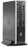
8. Route the cables through the slots beneath the drive cage (1), pull the assembly (right side first) into the chassis (2), and then remove the assembly from the computer. Figure 6-58 Routing the cables and removing the power switch assembly To install the front I/O and power switch assembly, reverse the removal procedure. NOTE: Be sure to correctly route the cables beneath the drive cage when reinstalling the assembly. Proper cable routing prevents damage to the cables and allows the drive cage to close properly. Front I/O, Power Switch Assembly 81
-
 1
1 -
2
-
3
-
4
-
5
-
6
-
7
-
8
-
9
-
10
-
11
-
12
-
13
-
14
-
15
-
16
-
17
-
18
-
19
-
20
-
21
-
22
-
23
-
24
-
25
-
26
-
27
-
28
-
29
-
30
-
31
-
32
-
33
-
34
-
35
-
36
-
37
-
38
-
39
-
40
-
41
-
42
-
43
-
44
-
45
-
46
-
47
-
48
-
49
-
50
-
51
-
52
-
53
-
54
-
55
-
56
-
57
-
58
-
59
-
60
-
61
-
62
-
63
-
64
-
65
-
66
-
67
-
68
-
69
-
70
-
71
-
72
-
73
-
74
-
75
-
76
-
77
-
78
-
79
-
80
-
81
-
82
-
83
-
84
-
85
-
 86
86 -
 87
87 -
 88
88 -
 89
89 -
 90
90 -
 91
91 -
 92
92 -
 93
93 -
 94
94 -
 95
95 -
 96
96 -
97
-
98
-
99
-
100
-
101
-
102
-
103
-
104
-
105
-
106
-
107
-
108
-
109
-
110
-
111
-
112
-
113
-
114
-
115
-
116
-
117
-
118
-
119
-
120
-
121
-
122
-
123
-
124
-
125
-
126
-
127
-
128
-
129
-
130
-
131
-
132
-
133
-
134
-
135
-
136
-
137
-
138
-
139
-
140
-
141
-
142
-
143
-
144
-
145
-
146
-
147
-
148
-
149
-
150
-
151
-
152
-
153
-
154
-
155
-
156
-
157
-
158
-
159
-
160
-
161
-
162
-
163
-
164
-
165
-
166
-
167
-
168
-
169
-
170
-
171
-
172
 |
 |

8.
Route the cables through the slots beneath the drive cage
(1)
, pull the assembly (right side first)
into the chassis
(2)
, and then remove the assembly from the computer.
Figure 6-58
Routing the cables and removing the power switch assembly
To install the front I/O and power switch assembly, reverse the removal procedure.
NOTE:
Be sure to correctly route the cables beneath the drive cage when reinstalling the assembly.
Proper cable routing prevents damage to the cables and allows the drive cage to close properly.
Front I/O, Power Switch Assembly
81