Hitachi C12LSH Instruction Manual
Hitachi C12LSH - 12" Dual Bevel Sliding Compound Miter Saw Manual
 |
UPC - 717709010338
View all Hitachi C12LSH manuals
Add to My Manuals
Save this manual to your list of manuals |
Hitachi C12LSH manual content summary:
- Hitachi C12LSH | Instruction Manual - Page 1
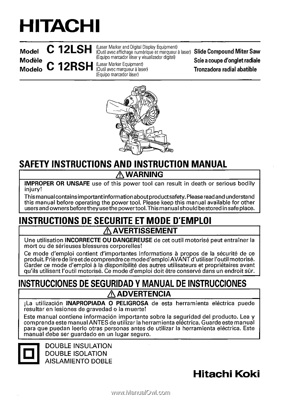
) Slide Compound Miter Saw C 12RSH Modele Modelo (Equipo marcador laser y visualizador digital) (Laser Marker Equipment) (Outil avec marqueur a laser) Scie a coupe d'onglet radiate Tronzadora radial abatible (Equipo marcador laser) e. eV-4ski014/i: 4 hi. 0•4 r -tt asti SAFETY INSTRUCTIONS - Hitachi C12LSH | Instruction Manual - Page 2
3 ACCESSORIES 13 MEANINGS OF SIGNAL WORDS 3 APPLICATIONS 14 SAFETY 4 PREPARATION BEFORE OPERATION 14 IMPORTANT SAFETY INSTRUCTIONS FOR BEFORE USING 15 USING ALL POWER TOOLS 4 BEFORE CUTTING 17 REPLACEMENT PARTS 8 PRACTICAL APPLICATIONS 25 USE PROPER EXTENSION CORD 8 SAW BLADE - Hitachi C12LSH | Instruction Manual - Page 3
or machine damage are identified by WARNINGS on the power tool and in this Instruction Manual. NEVER use this power tool in a manner that has not been specifically recommended by HITACHI. MEANINGS OF SIGNAL WORDS WARNING indicates a potentially hazardous situations which, if ignored, could result - Hitachi C12LSH | Instruction Manual - Page 4
POWER TOOLS READ ALL OF THE WARNINGS AND OPERATING INSTRUCTIONS IN THIS MANUAL BEFORE OPERATING OR MAINTAINING THIS TOOL: Q WARNING IN PLACE and in working order. 2. ALWAYS REMOVE ADJUSTING KEYS AND WRENCHES BEFORE STARTING TOOL. Always confirm that all keys and adjusting wrenches have been removed - Hitachi C12LSH | Instruction Manual - Page 5
injury or damage to the tool. 23. Never raise the saw blade from the workpiece until it has first come to a complete stop. 24. Always use outboard stands to provide support for long workpieces that overhang the table of the slide compound miter saw. 25. Always return the carriage to the full rear - Hitachi C12LSH | Instruction Manual - Page 6
23. Always use outboard stands to provide support for long workpieces that overhang the table of the slide compound miter saw. 24. Always operate the tool after ensuring the workpiece is fixed properly with a vise assembly. 25. The operating instructions provided with the tool shall direct the user - Hitachi C12LSH | Instruction Manual - Page 7
WARNING FOR YOUR OWN SAFETY READ THIS INSTRUCTION MANUAL BEFORE OPERATING THE SLIDE COMPOUND MITER SAW 1. Always wear eye protection when using the slide compound miter saw. 2. Always keep hands out of the path of the saw blade. 3. Never operate the saw without the guards in place. 4. Never perform - Hitachi C12LSH | Instruction Manual - Page 8
power before changing blade or servicing. 8. Saw blade diameter is 12" (305 mm). 9. No load speed is 3,800/min. 10. To reduce the risk of injury, return carriage to the full rear position after each crosscut operation. REPLACEMENT PARTS When servicing use only identical replacement parts. Repairs - Hitachi C12LSH | Instruction Manual - Page 9
in this Instruction Manual, including not using the power tool in wet environments. To keep the double insulation system effective, follow these precautions: * Only HITACHI AUTHORIZED SERVICE CENTER should disassemble or assemble this power tool, and only genuine HITACHI replacement parts should be - Hitachi C12LSH | Instruction Manual - Page 10
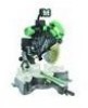
Instruction Manual may show details or attachments that differ from those on your own power tool. NAME OF PARTS MODEL C12LSH/MODEL C12RSH Digital display Motor Nameplate (only C12LSH) Gear case Motor head Dust bag Locking pin Handle Hinge Spindle cover Holder (A) Clamp lever Laser marker - Hitachi C12LSH | Instruction Manual - Page 11
5 mm machine screw Belt cover Spindle lock Adjuster (For laser marker) Trigger switch 0000 co Knob (A) Indicator (For left bevel scale) 0 on Fig. 2 English Slide securing knob (A) Slide securing knob (B) NOT Holder 11 - Hitachi C12LSH | Instruction Manual - Page 12
Left 0° - 45° Right 0° - 45° Compound sawing range Left (Bevel) 0° - 45°, Left (Miter) 0° - 45°, Right (Miter) 0° - 31° Right (Bevel) 0°- 45°, Right (Miter) 0° - 45°, Left (Miter) 0°- 31° Net weight C12LSH 66.1 lbs. (30 kg) C12RSH 63.9 lbs. (29 kg) Cord 2 Conductor type cable 6ft. (1.8 m) 12 - Hitachi C12LSH | Instruction Manual - Page 13
for this power tool are mentioned in this Instruction Manual. The use of any other attachment or accessory can be dangerous and could cause injury or mechanical damage. STANDARD ACCESSORIES IC) 12' (305 mm) TCT Saw blade (1 piece) (For wood) C) Dust bag (1 piece) 0 17 mm BOX wrench (1 piece - Hitachi C12LSH | Instruction Manual - Page 14
holder attached to the rear of the base helps stabilize the power tool. a7c ---1/ Holder adjustment: Loosen the 6 mm bolt with the 10 mm box wrench. Adjust the holder until its bottom surface contacts the work bench surface. After adjustment, firmly tighten the 6 6 mm mm bolt Bolt Move Holder - Hitachi C12LSH | Instruction Manual - Page 15
prepared for shipping, its main parts are secured by a locking dust bag, holder, stopper and vises (The holder and stopper are optional accessories.) Attach the dust bag saw blade for visible defects. Confirm that the saw blade is free of cracks or other visible damage. 4. Confirm that the saw blade - Hitachi C12LSH | Instruction Manual - Page 16
limit position of the Saw Blade. Although it was adjusted before shipment, carefully check the height of the saw blade. Confirm that the saw blade can be lowered 23/64 Repair or replace the receptacle if it is faulty. 9. Confirm the tool's power cord is not damaged. Repair or replace the power cord - Hitachi C12LSH | Instruction Manual - Page 17
insert for bevel angle cutting. 2. Checking the saw blade lower limit position Check that the saw blade can be lowered 23/64" to 7/16" (9 mm to 11 mm) below the table insert as shown in Fig. 9-a. When you replace a saw blade with a new one, adjust the lower limit position so that the saw blade will - Hitachi C12LSH | Instruction Manual - Page 18
mm depth z adjustment bolt C.1 0 Gear case Saw blade (1) Turn the 8 mm depth adjustment bolt, change the height where the bolt head and the hinge contacts, and adjust the lower limit position of the saw blade. -\\ Turntable Fig. 9-a Turn NOTE: Confirm that the saw blade is adjusted so that - Hitachi C12LSH | Instruction Manual - Page 19
screw, 8 mm bolt (A) and 8 mm bolt (B). When changing the adjustment, change the height of the 8 mm set screw, 8 mm bolt (A), or 8 mm bolt (B) by turning them. When changing the bevel angle to the right 45°, pull the set pin (A) on the direction shown in Fig. 12-b and incline the motor head to the - Hitachi C12LSH | Instruction Manual - Page 20
bevel angle) Fig. 12-b 7. Securing the workpiece WARNING: Always clamp or vise to secure the workpiece to the fence; otherwise the workpiece might be thrust from the table and cause bodily harm. 8. Installing the holders ... (Optional accessory) 6 mm knob bolt Steel (Optional accessory) square - Hitachi C12LSH | Instruction Manual - Page 21
off. * Exercise utmost caution in handling a switch trigger for the position adjustment of the laser line, as the power plug is plugged into the receptacle during operation. If the switch trigger is pulledinadvertently,the saw blade can rotate and result in unexpected accidents. * Do not remove the - Hitachi C12LSH | Instruction Manual - Page 22
turn the adjuster and shift the laser line. (If you turn the adjuster clockwise, the laser line will shift to the right and if you turn it counterclockwise, the laser line will shift to the left.) When you work with the ink line aligned with the left side of the saw blade, align the laser line with - Hitachi C12LSH | Instruction Manual - Page 23
the ink line, slide the workpiece little by little and secure it by vise at a position where the laser line overlaps with the ink line. Work on the grooving again and check the position of the laser line. If you wish to change the laser line's position, make adjustments again following the steps - Hitachi C12LSH | Instruction Manual - Page 24
the top limit position and the blade stopped. NOTE: • Before starting to cut, align the main unit to the miter angle 0° and the bevel angle 0° and hold down thier will not match. • The laser marker will not light up if the digital display switch is turned off. (only on C12LSH) • Do not use the main - Hitachi C12LSH | Instruction Manual - Page 25
English PRACTICAL APPLICATIONS &WARNING: * To avoid personal injury, never remove or place a workpiece on the table while the tool is being operated. * Never place your limbs inside of the line next to warning sign while the tool is being operated. This may cause hazardous conditions (see Fig. 23). - Hitachi C12LSH | Instruction Manual - Page 26
Assembly (Standard accessory) 6mm wing Adjusting line saw blade is the width of the cut. Therefore, slide the workpiece to the right (viewed from the operator's 0 0 0 position) when length is desired, or to the left when length ® is desired. If a laser marker is used, align the • laser - Hitachi C12LSH | Instruction Manual - Page 27
switch off, and check that the saw blade has stopped. Then raise the handle, slide securing knob (A)/(B) (see Fig. 2) as indicated in Fig. 27. t Press Lower the handle to cut the workpiece. down Using the power tool this way will permit cutting of workpieces of up to 4-3/16" (107 mm) square - Hitachi C12LSH | Instruction Manual - Page 28
12-1/4" (312 mm) wide: Handle Loosen the slide securing knob (A) (see t C) Press Fig. 2), grip the handle and slide the saw * down blade forward. Then press down on the handle and slide the saw blade a workpiece of 4-3/4" (120 mm) height, adjust the lower limit position of the motor head so - Hitachi C12LSH | Instruction Manual - Page 29
the rear. The clamp lever adopts a latchet system. When contacting the work bench and the main body, pull the clamp lever in the direction of the arrow mark as illustrated in Fig. 30, and change the direction of the clamp lever. (2) Adjust the bevel angle to the desired setting while watching the - Hitachi C12LSH | Instruction Manual - Page 30
to tighten the motor head section enough so it will not move. (2) When making fine adjustments of the bevel angle, turn the knob (B) while supporting the handle with your hand. NOTE: Turning knob (B) clockwise, allows fine adjustment of the main unit to the left (as seen from front). Turning knob - Hitachi C12LSH | Instruction Manual - Page 31
are properly aligned. * Operation of the saw with the miter scale and indicator out of alignment, or with the side handle not properly tightened, will result in poor cutting precision. 10. Miter angle fine adjustment (1) Rotate the turntable to the miter angle you need. (2) When making fine - Hitachi C12LSH | Instruction Manual - Page 32
be performed by following the instructions in 7 and 10 above. For maximum dimensions for compound cutting, refer to "SPECIFICATIONS" table on page 12. &CAUTION: Always secure the workpiece with the right or left hand and cut it by sliding the round portion of the saw backwards with the left hand - Hitachi C12LSH | Instruction Manual - Page 33
are properly aligned. Then tighten the clamp lever. To process crown molding at • Type of Crown positions ® and ® in Fig. 38. Molding Miter Angle Bevel Angle Setting Setting 45° Type right 35.3° ( I mark) left 30° ( I mark) 38° Type right 31.6° ( 1 mark) left 33.9° (1mark) To process - Hitachi C12LSH | Instruction Manual - Page 34
the lower surface (® in Fig. 37) contacts the fence as in Fig. 42. Head Head N 0 Bevel angle scale 4 Fence (A) no, Bevel angle scale 2 Fence (B) J. Miter angle scale / Turntable Fig. 39 Fence Base 9 II;or Miter angle scale Turntable Base Fig. 40 Fence- Table on base Fig. 41 Table on - Hitachi C12LSH | Instruction Manual - Page 35
Turntable Base Fig. 43 Base Miter angle scale Turntable Fig. 44 Fence Fence Table on base Fig. 45 Table on base Fig. 46 Cutting method of crown molding without tilting the saw blade (1) Crown molding Stopper (L) and (R) Crown molding vise ass'y (optional accessories) Crown molding stopper - Hitachi C12LSH | Instruction Manual - Page 36
vise ass'y to a position where it will not contact the saw blade. Position crown molding with its WALL CONTACT EDGE against the guide fence and its CEILING CONTACT EDGE against the crown molding Stoppers as shown in Fig. 47-b. Adjust the crown molding Stoppers according to the size of the crown - Hitachi C12LSH | Instruction Manual - Page 37
in Fig. 49. Lower the motor head, and turn the 6 mm depth adjustment bolt by hand. (Where the head of the 6 mm depth adjustment bolt contacts the hinge.) (2) Adjust to the desired cutting depth by setting the distance between the saw blade and the surface of the turntable (see b in Fig. 48). NOTE - Hitachi C12LSH | Instruction Manual - Page 38
dust bag (Standard accessory) Dust bag O Duct (1) When the dust bag has become full of sawdust, dust will be blown out of the dust bag when the saw blade rotates. Check the dust bag periodically and empty it before it becomes full. 1 (2) During bevel and compound cutting, attach the dust bag - Hitachi C12LSH | Instruction Manual - Page 39
left by 17 mm box wrench (Standard accessorie) as indicated in Fig. 52-c. & CAUTION: *A dust guide is installed inside behind the hinge. When removing or installing the saw blade, do not make contact with the dust guide. Contact may break or chip saw blade tips. *Confirm that the spindle lock has - Hitachi C12LSH | Instruction Manual - Page 40
the saw blade Always replace the saw blade immediately upon the first sign of deterioration or damage. A damaged saw blade can cause personal injury and a worn saw blade can cause ineffective operation and possible overload to the motor. &CAUTION: Never use a dull saw blade. When a saw blade is - Hitachi C12LSH | Instruction Manual - Page 41
any loose part. & Replacement of Poly-V-Belt Poly-V-belt Pulley (A) 0 O Pulley (B) Fig. 55 The power of the motor is transmitted to the saw blade by a Poly-V-Belt. When the Poly-VBelt is broken or damaged, remove the belt belt to the pulleys. 8. Lubrication Lubricate the following sliding - Hitachi C12LSH | Instruction Manual - Page 42
replacement parts will be used and that the double insulation system will be protected, all service (other than routine maintenance) must be performed by an AUTHORIZED HITACHI POWER TOOL REPAIR CENTER ONLY. NOTE: Specifications are subject to change without any obligation on the part of HITACHI
-
 1
1 -
 2
2 -
 3
3 -
 4
4 -
 5
5 -
 6
6 -
 7
7 -
8
-
9
-
10
-
11
-
12
-
13
-
14
-
15
-
16
-
17
-
18
-
19
-
20
-
21
-
22
-
23
-
24
-
25
-
26
-
27
-
28
-
29
-
30
-
31
-
32
-
33
-
34
-
35
-
36
-
37
-
38
-
39
-
40
-
41
-
42
 |
 |
HITACHI
Model
C
12LSFI
(Laser
Marker
and
Digital
Display
Equipment)
(Outil
avec
affichage
numarique
et
marqueur
a
laser)
Slide
Compound
Miter
Saw
(Equipo
marcador
laser
y
visualizador
digital)
Modele
(Laser
Marker
Equipment)
Scie
a
coupe
d'onglet
radiate
Modelo
C
12RSH
(Outil
avec
marqueur
a
laser)
Tronzadora
radial
abatible
(Equipo
marcador
laser)
e
.
e-40:
0•
4
Vii
4
s
k1
/
4
hi.
r
tt
—
asti
SAFETY
INSTRUCTIONS
AND
INSTRUCTION
MANUAL
&
WARNING
IMPROPER
OR
UNSAFE
use
of
this
power
tool
can
result
in
death
or
serious
bodily
injury!
This
manualcontains
importantinformation
aboutproductsafety.
Please
read
and
understand
this
manual
before
operating
the
power
tool.
Please
keep
this
manual
available
for
other
users
and
owners
beforethey
usethe
powertool.
This
manual
should
bestored
in
safe
place.
INSTRUCTIONS
DE
SECURITE
ET
MODE
D'EMPLOI
&
AVERTISSEMENT
Une
utilisation
INCORRECTE
OU
DANGEREUSE
de
cet
outil
motorise
peut
entrainer
la
mort
ou
de
serieuses
blessures
corporelles!
Ce
mode
d'emploi
contient
d'importantes
informations
a
propos
de
la
securite
de
ce
produit.
Priere
de
lire
et
de
connprendrece
mode
d'emploi
AVANT
d'utiliser
l'outil
motorise.
Garder
ce
mode
d'emploi
a
la
disponibilite
des
autres
utilisateurs
et
proprietaires
avant
qu'ils
utilisent
l'outil
motorise.
Ce
mode
d'emploi
doit
etre
conserve
dans
un
endroit
sir.
INSTRUCCIONES
DE
SEGURIDAD
Y
MANUAL
DE
INSTRUCCIONES
&
ADVERTENCIA
i
La
utilizaciOn
INAPROPIADA
0
PELIGROSA
de
esta
herramienta
electrica
puede
resultar
en
lesiones
de
gravedad
o
la
muerte!
Este
manual
contiene
informaci6n
importante
sobre
la
seguridad
del
producto.
Lea
y
comprenda
este
manual
ANTES
de
utilizar
la
herramienta
electrica.
Guarde
este
manual
para
que
puedan
leerlo
otras
personas
antes
de
utilizar
la
herramienta
electrica.
Este
manual
debe
ser
guardado
en
un
lugar
seguro.
0
DOUBLE
INSULATION
DOUBLE
ISOLATION
AISLAMIENTO
DOBLE
Hitachi
Koki