Hitachi C12LSH Instruction Manual - Page 33
Hitachi C12LSH - 12" Dual Bevel Sliding Compound Miter Saw Manual
 |
UPC - 717709010338
View all Hitachi C12LSH manuals
Add to My Manuals
Save this manual to your list of manuals |
Page 33 highlights
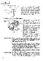
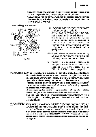
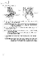
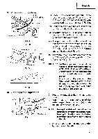
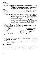
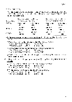
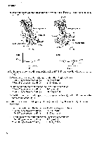
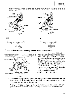
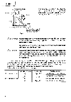
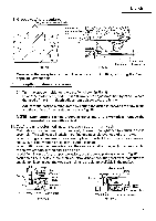
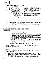
English For bevel cut setting Turn the clamp lever on bevel section to the left and check that the position is stable and that the bevel angle scale and the tip of the indicator are properly aligned. Then tighten the clamp lever. To process crown molding at • Type of Crown positions ® and ® in Fig. 38. Molding Miter Angle Bevel Angle Setting Setting 45° Type right 35.3° ( I mark) left 30° ( I mark) 38° Type right 31.6° ( 1 mark) left 33.9° (1mark) To process crown molding at positions C) and C) in Fig. 38. Miter Angle Setting Bevel Angle Setting left 35.3° (I mark) left 30° (I mark) left 31.6° ( 1 mark) left 33.9° ( 1 mark) (1) Setting to cut crown moldings at positions® and ® in Fig. 38 (see Fig. 39; tilt the motor head to the left): ® Turn the turntable to the right and set the Miter Angle as follows: * For 45° type crown moldings: 35.3° (I mark) * For 38° type crown moldings: 31.6° ( 1 mark) ® Tilt the motor head to the left and set the Bevel Angle as follows: * For 45° type crown moldings: 30° (I mark) * For 38° type crown moldings: 33.9° ( 1 mark) ® Position the crown molding so that the upper surface (A in Fig. 37) contacts the fence as indicated in Fig. 41. (2) Setting to cut crown moldings at positions 0 and ® in Fig. 38 (see Fig. 40; tilt the head to the left): ® Turn the turntable to the left and set the Miter Angle as follows: * For 45° type crown moldings: 35.3° (I mark) * For 38° type crown moldings: 31.6° ( 1 mark) C) Tilt the head to the left and set the Bevel Angle as follows: * For 45° type crown moldings: 30° (I mark) * For 38° type crown moldings: 33.9° ( 1 mark) 33
-
 1
1 -
2
-
3
-
4
-
5
-
6
-
7
-
8
-
9
-
10
-
11
-
12
-
13
-
14
-
15
-
16
-
17
-
18
-
19
-
20
-
21
-
22
-
23
-
24
-
25
-
26
-
27
-
 28
28 -
 29
29 -
 30
30 -
 31
31 -
 32
32 -
 33
33 -
 34
34 -
 35
35 -
 36
36 -
 37
37 -
 38
38 -
39
-
40
-
41
-
42
 |
 |
