Hitachi C12LSH Instruction Manual - Page 23
Digital, Display, Panel, C12lsh
 |
UPC - 717709010338
View all Hitachi C12LSH manuals
Add to My Manuals
Save this manual to your list of manuals |
Page 23 highlights
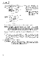
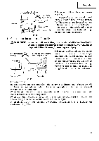
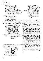
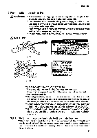
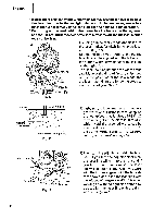
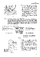
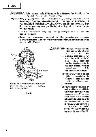
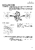
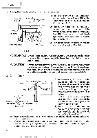
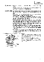
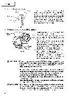
English ~\ Laser line Marking (pre-marked Fig. 20 (3) After adjusting the position of the laser line, draw a right-angle ink line on the workpiece and align the ink line with the laser line. When aligning the ink line, slide the workpiece little by little and secure it by vise at a position where the laser line overlaps with the ink line. Work on the grooving again and check the position of the laser line. If you wish to change the laser line's position, make adjustments again following the steps from (1) to (3). NOTE: Check and make sure on a periodic basis if the position of the laser line is in order. As regards the checking method, draw a right-angle ink line on the workpiece with the height of about 25/32" (20 mm) and the width of 5-29/ 32"(150 mm), and check that the laser line is in line with the ink line [The deviation between the ink line and the laser line should be less than the ink line width (0.5 mm►]. (Fig. 20) 11. DIGITAL DISPLAY PANEL (for C12LSH) Miter angle window (Displays arrows show angle and direction that turntable is rotating. Left is .) Bevel angle window (Displays arrows showing motor head bevel angle and bevel direction. Left is .) Miter angle reset button RESET ItiCK UNIT RESET Bevel angle reset button Fig. 21 Back light ON/OFF switch (Press and the switch illuminates. Press again and the lighting turns off.) (1) Turning on the digital display switch shows 0° for both miter and bevel angle, regardless of main unit angle. (2) Align the main unit angle with the tilt angle (01 and miter angle (0°) and hold down their reset buttons for at least 0.2 second. II (3) Turning on the laser marker switch while the digital display switch is on, lights up Digital display switch Laser marker switch (for C12LSH) (Also serves as laser marker power switch.) Fig. 22-a the laser marker. (On the C12RSH, only the laser marker switch.) 23
-
 1
1 -
2
-
3
-
4
-
5
-
6
-
7
-
8
-
9
-
10
-
11
-
12
-
13
-
14
-
15
-
16
-
17
-
 18
18 -
 19
19 -
 20
20 -
 21
21 -
 22
22 -
 23
23 -
 24
24 -
 25
25 -
 26
26 -
 27
27 -
 28
28 -
29
-
30
-
31
-
32
-
33
-
34
-
35
-
36
-
37
-
38
-
39
-
40
-
41
-
42
 |
 |
