Hitachi C12LSH Instruction Manual - Page 34
Bevel, angle, scale, Fence, Miter, II;or, Turntable, Table
 |
UPC - 717709010338
View all Hitachi C12LSH manuals
Add to My Manuals
Save this manual to your list of manuals |
Page 34 highlights
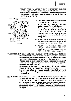
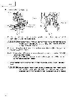
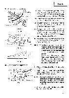
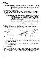
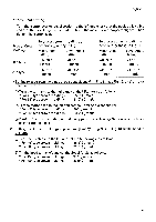
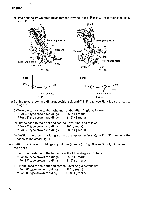
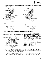
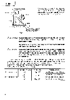
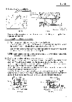
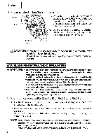
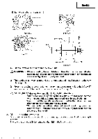
English Position the crown molding so that the lower surface (® in Fig. 37) contacts the fence as in Fig. 42. Head Head N 0 Bevel angle scale 4 Fence (A) no, Bevel angle scale 2 Fence (B) J. Miter angle scale / Turntable Fig. 39 Fence Base 9 II;or Miter angle scale Turntable Base Fig. 40 Fence- Table on base Fig. 41 Table on base Fig. 42 (3) Setting to cut crown moldings at positions ® and ® in Fig. 38 (see Fig. 43; tilt the head to the right): C) Turn the turntable to the right and set the Miter Angle as follows: * For 45° type crown moldings: 35.3° ( j mark) * For 38° type crown moldings: 31.6° (I. mark) 0 Tilt the head to the right and set the Bevel Angle as follows: * For 45° type crown moldings: 30° ( I mark) * For 38° type crown moldings: 33.9° ( j mark) C) Position the crown molding so that the upper surface (C) in Fig. 37) contacts the fence as indicated Fig. 45. (4) Setting to cut crown moldings at positions 0 and C) in Fig. 38 (see Fig. 44; tilt the head to the right): ® Turn the turntable to the left and set the Miter Angle as follows: * For 45° type crown moldings: 35.3° (j mark) * For 38° type crown moldings: 31.6° ( j mark) C) Tilt the head to the right and set the Bevel Angle as follows: * For 45° type crown moldings: 30° ( j mark) * For 38° type crown moldings: 33.9° ( j mark) 34
-
 1
1 -
2
-
3
-
4
-
5
-
6
-
7
-
8
-
9
-
10
-
11
-
12
-
13
-
14
-
15
-
16
-
17
-
18
-
19
-
20
-
21
-
22
-
23
-
24
-
25
-
26
-
27
-
28
-
 29
29 -
 30
30 -
 31
31 -
 32
32 -
 33
33 -
 34
34 -
 35
35 -
 36
36 -
 37
37 -
 38
38 -
 39
39 -
40
-
41
-
42
 |
 |
