Hitachi C12LSH Instruction Manual - Page 35
accessories
 |
UPC - 717709010338
View all Hitachi C12LSH manuals
Add to My Manuals
Save this manual to your list of manuals |
Page 35 highlights
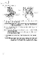
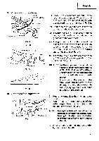
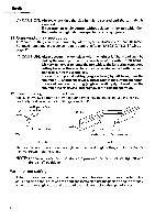
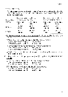
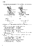
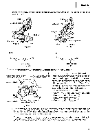
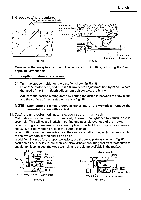
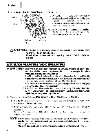
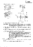
English C) Position the crown molding so that the lower surface (® in Fig. 37) contacts the fence as in Fig. 46. Header Bevel angle scale Head 0 Bevel angle scale 0 Fence (A) 0 Fence (B) 3 Miter angle scale Turntable Base Fig. 43 Base Miter angle scale Turntable Fig. 44 Fence Fence Table on base Fig. 45 Table on base Fig. 46 Cutting method of crown molding without tilting the saw blade (1) Crown molding Stopper (L) and (R) Crown molding vise ass'y (optional accessories) Crown molding stopper (R) (optional accessories) 6mm knob 6mm knob bolt bolt (optional accessories) allow easier cuts of crown molding without tilting the saw blade. Install them in the base both-sides side to be shown in Fig. 47-a. After inserting Tighten the 6mm knob bolts to secure the crown molding Stoppers. O [Optional accessories used] • Crown molding Vise Ass'y (Include Crown molding Stopper (L)) • Crown molding Stopper (L) Crown molding stopper (L) 6mm wing bolt (Optional accessories) • Crown molding Stopper (R) Fig. 47-a (2) The crown molding vise (B) (Optional accessory) can be mounted on either the left fence (Fence (B)) or the right fence (Fence (A)). It can unite with the slope of the crown molding and vice can be pressed down. Then turn the upper knob, as necessary, to securely attach the crown molding in position. To raise or lower the vise assembly, first loosen the 6mm knob bolt. 35
-
 1
1 -
2
-
3
-
4
-
5
-
6
-
7
-
8
-
9
-
10
-
11
-
12
-
13
-
14
-
15
-
16
-
17
-
18
-
19
-
20
-
21
-
22
-
23
-
24
-
25
-
26
-
27
-
28
-
29
-
 30
30 -
 31
31 -
 32
32 -
 33
33 -
 34
34 -
 35
35 -
 36
36 -
 37
37 -
 38
38 -
 39
39 -
 40
40 -
41
-
42
 |
 |
