Hitachi C12LSH Instruction Manual - Page 22
Switch, Laser, Workpiece, blade, Marking, marked, Cutting, width, assembly, Groove, Adjuster
 |
UPC - 717709010338
View all Hitachi C12LSH manuals
Add to My Manuals
Save this manual to your list of manuals |
Page 22 highlights
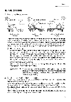
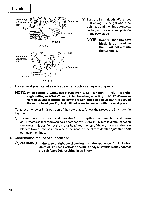
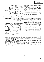
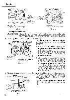
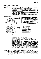
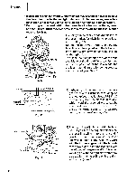
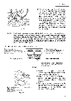
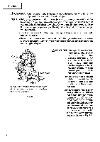
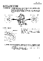
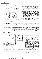
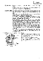
English *In outdoor or near-the-window operations,itmay become difficult to observe the laser line due to the sunlight. Under such circumstances, move to a place that is not directly under the sunlight and engage in the operation. * Do not tug on the cord behind the motor head or hook your finger, wood and the like around it; otherwise, the cord may come off and the laser marker may not be lit up. Switch Ink lining can be easily made on this tool to the laser marker. A switch lights up the laser marker. (Fig. 17) Depending upon your cutting choice, the laser line can be aligned with the left side of the cutting width (saw blade) or the ink line 0 6 Laser line on the right side. The laser line is adjusted to the width of the saw blade at the time of factory shipment. Adjust the positions of the saw blade and the laser line taking the following steps to suit the use of your choice. Workpiece Marking (pre-marked) Fig. 17 Saw blade Cutting width Fig. 18 (1) Light up the laser marker and make a groove of about 3/16" (5 mm) deep on the workpiece that is about 25/32" (20 mm) in height and 5-29/32"(150 mm) in width. Hold the grooved workpiece by vise as it is and do not move it. For grooving work, refer to "13.G roove cutting procedures" on page 37. Vise assembly Move---73, A 4 Turn Laser line 77-7,7-Groove Adjuster Fig. 19 (2) Then, turn the adjuster and shift the laser line. (If you turn the adjuster clockwise, the laser line will shift to the right and if you turn it counterclockwise, the laser line will shift to the left.) When you work with the ink line aligned with the left side of the saw blade, align the laser line with the left end of the groove. (Fig. 19) When you align it with the right side of the saw blade, align the laser line with the right side of the groove. 22
-
 1
1 -
2
-
3
-
4
-
5
-
6
-
7
-
8
-
9
-
10
-
11
-
12
-
13
-
14
-
15
-
16
-
 17
17 -
 18
18 -
 19
19 -
 20
20 -
 21
21 -
 22
22 -
 23
23 -
 24
24 -
 25
25 -
 26
26 -
 27
27 -
28
-
29
-
30
-
31
-
32
-
33
-
34
-
35
-
36
-
37
-
38
-
39
-
40
-
41
-
42
 |
 |
