Hitachi C12LSH Instruction Manual - Page 39
Vacc?
 |
UPC - 717709010338
View all Hitachi C12LSH manuals
Add to My Manuals
Save this manual to your list of manuals |
Page 39 highlights
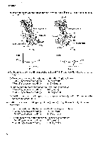
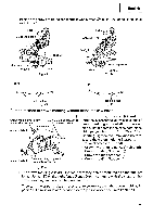
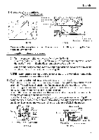
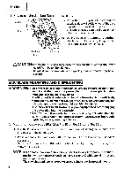
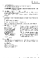
(3) Remove the bolt and washer (D) / '0 VACC? 5 mm screw English Spindle cover Fig. 52-a Tighten Washer (B) {-dirt 10 mm bolt Bolt Loosen Spindle lock Fig. 52-b Saw Blade E U) Fig. 52-c Washer (B) Washer (A) (4) Lift the lower guard and mount the saw blade. Fig. 52-d & WARNING: When mounting the saw blade, confirm that the rotation indicator mark on the saw blade and the rotation direction of the spindbe cover (see Fig. 1) are properly matched. (5) Thoroughly clean washer (B) and the 10 mm bolt, and install them onto the saw blade spindle. (6) Press in the spindle lock and tighten the 10 mm bolt by turning it to the left by 17 mm box wrench (Standard accessorie) as indicated in Fig. 52-c. & CAUTION: *A dust guide is installed inside behind the hinge. When removing or installing the saw blade, do not make contact with the dust guide. Contact may break or chip saw blade tips. *Confirm that the spindle lock has returned to the retract position after installing or removing the saw blade. *Tighten the 10 mm bolt so it does not come loose during operation. Confirm the 10 mm bolt has been properly tightened before the power tool is started. 2. Dismounting the saw blade Dismount the saw blade by reversing the mounting procedures described in paragraph 1 above. The saw blade can easily be removed after lifting the lower guard. 39
-
 1
1 -
2
-
3
-
4
-
5
-
6
-
7
-
8
-
9
-
10
-
11
-
12
-
13
-
14
-
15
-
16
-
17
-
18
-
19
-
20
-
21
-
22
-
23
-
24
-
25
-
26
-
27
-
28
-
29
-
30
-
31
-
32
-
33
-
 34
34 -
 35
35 -
 36
36 -
 37
37 -
 38
38 -
 39
39 -
 40
40 -
 41
41 -
 42
42
 |
 |
