IBM 84802AX Installation Guide - Page 23
Installing an adapter
 |
View all IBM 84802AX manuals
Add to My Manuals
Save this manual to your list of manuals |
Page 23 highlights
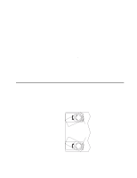
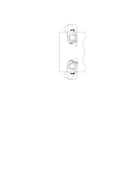
• If you are installing an adapter that will control your startup (boot) drive, install the adapter in PCI expansion slot 2. • PCI expansion slots 1 through 5 are on PCI bus 0. The system scans the AGP slot and PCI expansion slots 1 through 5 to assign system resources; then, the system starts (boots) devices in the following order, if you have not changed the default boot sequence: the AGP slot, PCI expansion slots 1 through 5; then, the system board integrated drive electronics (IDE) or SCSI devices. • For a list of supported options for your server, go to http://www.ibm.com/pc/compat/ on the World Wide Web. Installing an adapter Complete the following steps to install an adapter. Attention: When you handle static-sensitive devices, take precautions to avoid damage from static electricity. For details about handling these devices, see "Handling static-sensitive devices" on page 6. 1. Review the safety precautions listed in "Safety" on page v. 2. Turn off the server and peripheral devices and disconnect all external cables and power cords; then, remove the side cover. For more information about removing the side cover, see "Removing the side cover" on page 8. 3. Remove the frame-support bracket. See "Removing the frame-support bracket" on page 9. 4. If you are installing a full-length adapter, rotate the front adapter-support bracket to the open (unlocked) position. 5. Rotate the rear adapter-retaining bracket to the open (unlocked) position, and then remove it from the server. 6. Remove the PCI expansion-slot cover. From the rear of the server, press in on the slot cover. Grasp it and pull it out of the slot. Store it in a safe place for future use. Attention: PCI expansion-slot covers must be installed on all vacant slots. This maintains the electronic emissions characteristics of the server and ensures proper cooling of server components. 7. Touch the static-protective package containing the adapter to any unpainted metal surface on the server. Then, remove the adapter from the static-protective package. Avoid touching the components and gold-edge connectors on the adapter. 8. Place the adapter on a flat, static-protective surface, and set any jumpers or switches as described by the adapter manufacturer. Chapter 2. Installing options 11
-
 1
1 -
2
-
3
-
4
-
5
-
6
-
7
-
8
-
9
-
10
-
11
-
12
-
13
-
14
-
15
-
16
-
17
-
 18
18 -
 19
19 -
 20
20 -
 21
21 -
 22
22 -
 23
23 -
 24
24 -
 25
25 -
 26
26 -
 27
27 -
 28
28 -
29
-
30
-
31
-
32
-
33
-
34
-
35
-
36
-
37
-
38
-
39
-
40
-
41
-
42
-
43
-
44
-
45
-
46
-
47
-
48
-
49
-
50
-
51
-
52
-
53
-
54
-
55
-
56
-
57
-
58
-
59
-
60
-
61
-
62
-
63
-
64
-
65
-
66
-
67
-
68
-
69
-
70
-
71
-
72
-
73
-
74
-
75
-
76
-
77
-
78
 |
 |
