Intel D925XECV2 English Manual Product Guide - Page 34
Installing and Removing Memory
 |
View all Intel D925XECV2 manuals
Add to My Manuals
Save this manual to your list of manuals |
Page 34 highlights
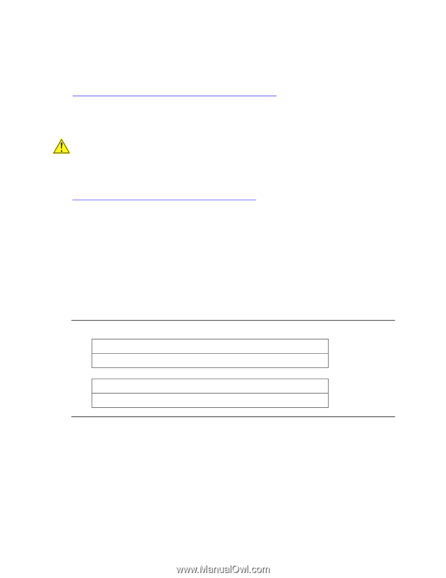
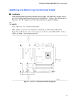
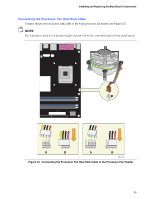
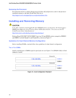
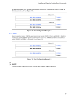
Intel Desktop Board D925XECV2/D925XEBC2 Product Guide Removing the Processor For instruction on how to remove the processor fan heat sink and processor, refer to the processor installation manual or the Intel World Wide Web site at: http://support.intel.com/support/processors/pentium4/inuse.htm Installing and Removing Memory CAUTION To be fully compliant with all applicable Intel SDRAM memory specifications, the board requires DIMMs that support the Serial Presence Detect (SPD) data structure. You can access the PC Serial Presence Detect Specification at: http://www.intel.com/technology/memory/pcsdram/spec/ Desktop Board D925XECV2/D925XEBC2 has four 240-pin DIMM sockets arranged as DIMM 0 and DIMM 1 in both Channel A and Channel B, as shown in Figure 17. Guidelines for Dual Channel Memory Configuration Before installing DIMMs, read and follow these guidelines for dual channel configuration. Two or Four DIMMs Install a matched pair of DIMMs equal in speed and size (see Figure 13) in DIMM 0 (blue) of both channels A and B. 1 GB, 400 MHz 1 GB, 400 MHz Channel A Channel B DIMM 0 DIMM 1 DIMM 0 DIMM 1 Figure 13. Dual Configuration Example 1 34
-
 1
1 -
2
-
3
-
4
-
5
-
6
-
7
-
8
-
9
-
10
-
11
-
12
-
13
-
14
-
15
-
16
-
17
-
18
-
19
-
20
-
21
-
22
-
23
-
24
-
25
-
26
-
27
-
28
-
 29
29 -
 30
30 -
 31
31 -
 32
32 -
 33
33 -
 34
34 -
 35
35 -
 36
36 -
 37
37 -
 38
38 -
 39
39 -
40
-
41
-
42
-
43
-
44
-
45
-
46
-
47
-
48
-
49
-
50
-
51
-
52
-
53
-
54
-
55
-
56
-
57
-
58
-
59
-
60
-
61
-
62
-
63
-
64
-
65
-
66
-
67
-
68
-
69
-
70
-
71
-
72
-
73
-
74
 |
 |