Intel D925XECV2 English Manual Product Guide - Page 46
Front Panel Header, Alternate Power LED Header, Chassis Intrusion Header
 |
View all Intel D925XECV2 manuals
Add to My Manuals
Save this manual to your list of manuals |
Page 46 highlights
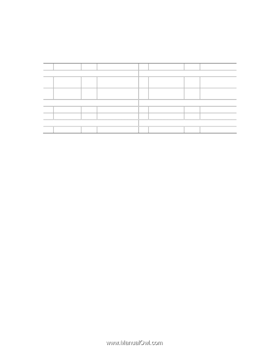
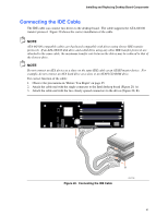
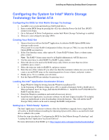
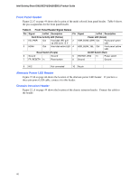
Intel Desktop Board D925XECV2/D925XEBC2 Product Guide Front Panel Header Figure 22, C on page 44 shows the location of the multi-colored front panel header. Table 8 shows the pin assignments for the front panel header. Table 8. Front Panel Header Signal Names Pin Signal In/Out Description Hard Drive Activity LED (Yellow) 1 HD_PWR Out Hard disk LED pullup (330 Ω) to +5 V 3 HDA# Out Hard disk active LED Pin Signal In/Out Description Power LED (Green) 2 HDR_BLNK_GRN Out Front panel green LED 4 HDR_BLNK_YEL Out Front panel yellow LED Reset Switch (Purple) On/Off Switch (Red) 5 Ground 7 FP_RESET# In Ground Reset switch 6 SWITCH_ON# In 8 Ground Power switch Ground 9 N/C Not connected 10 No pin Alternate Power LED Header Figure 22, B on page 44 shows the location of the alternate power LED header. If you have a three-pin power LED cable, connect it to this header. Chassis Intrusion Header Figure 22, A on page 44 shows the location of the chassis intrusion header. Connect the cable to the header. 46
-
 1
1 -
2
-
3
-
4
-
5
-
6
-
7
-
8
-
9
-
10
-
11
-
12
-
13
-
14
-
15
-
16
-
17
-
18
-
19
-
20
-
21
-
22
-
23
-
24
-
25
-
26
-
27
-
28
-
29
-
30
-
31
-
32
-
33
-
34
-
35
-
36
-
37
-
38
-
39
-
40
-
 41
41 -
 42
42 -
 43
43 -
 44
44 -
 45
45 -
 46
46 -
 47
47 -
 48
48 -
 49
49 -
 50
50 -
 51
51 -
52
-
53
-
54
-
55
-
56
-
57
-
58
-
59
-
60
-
61
-
62
-
63
-
64
-
65
-
66
-
67
-
68
-
69
-
70
-
71
-
72
-
73
-
74
 |
 |