Intel D925XECV2 English Manual Product Guide - Page 53
Installing Other Connectors
 |
View all Intel D925XECV2 manuals
Add to My Manuals
Save this manual to your list of manuals |
Page 53 highlights
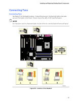
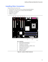
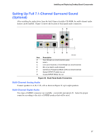
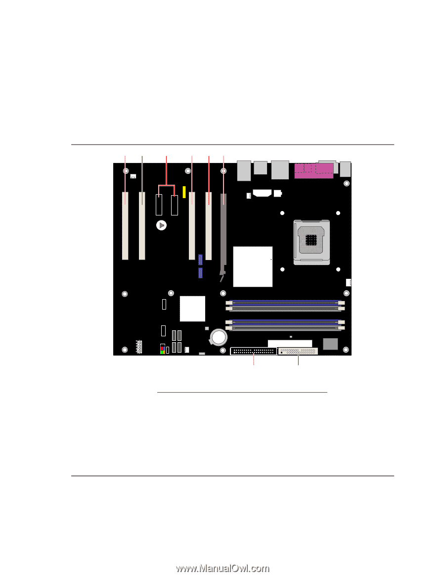
Installing and Replacing Desktop Board Components Installing Other Connectors Figure 29 shows the location of the: • PCI bus add-in card connectors (two on Desktop Board D925XEBC2) • PCI Express x1 connectors (one on Desktop Board D925XEBC2) • PCI Express x16 connector • Floppy drive connector • IDE drive connector AB C D EF H G Item Description A PCI bus add-in card connector 4 B PCI bus add-in card connector 3 C PCI Express x1 connectors D PCI bus add-in card connector 2 (SMBus routed) E PCI bus add-in card connector 1 F PCI Express x16 connector G Floppy drive connector H IDE drive connector Figure 29. Location of Other Connectors OM16933 53
-
 1
1 -
2
-
3
-
4
-
5
-
6
-
7
-
8
-
9
-
10
-
11
-
12
-
13
-
14
-
15
-
16
-
17
-
18
-
19
-
20
-
21
-
22
-
23
-
24
-
25
-
26
-
27
-
28
-
29
-
30
-
31
-
32
-
33
-
34
-
35
-
36
-
37
-
38
-
39
-
40
-
41
-
42
-
43
-
44
-
45
-
46
-
47
-
 48
48 -
 49
49 -
 50
50 -
 51
51 -
 52
52 -
 53
53 -
 54
54 -
 55
55 -
 56
56 -
 57
57 -
 58
58 -
59
-
60
-
61
-
62
-
63
-
64
-
65
-
66
-
67
-
68
-
69
-
70
-
71
-
72
-
73
-
74
 |
 |
Installing and Replacing Desktop Board Components
53
Installing Other Connectors
Figure 29 shows the location of the:
•
PCI bus add-in card connectors (two on Desktop Board D925XEBC2)
•
PCI Express x1 connectors (one on Desktop Board D925XEBC2)
•
PCI Express x16 connector
•
Floppy drive connector
•
IDE drive connector
OM16933
A
B
C
D
E
G
H
F
Item Description
A
PCI bus add-in card connector 4
B
PCI bus add-in card connector 3
C
PCI Express x1 connectors
D
PCI bus add-in card connector 2 (SMBus routed)
E
PCI bus add-in card connector 1
F
PCI Express x16 connector
G
Floppy drive connector
H
IDE drive connector
Figure 29.
Location of Other Connectors