Intel DG965WH Product Specification - Page 47
PCI Configuration Space Map
 |
View all Intel DG965WH manuals
Add to My Manuals
Save this manual to your list of manuals |
Page 47 highlights
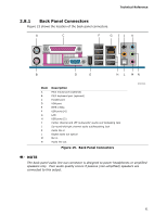
Technical Reference 2.4 PCI Configuration Space Map Table 14. PCI Configuration Space Map Bus Device Function Number (hex) Number (hex) Number (hex) Description 00 00 00 Memory controller of Intel 82G965 component 00 01 00 PCI Express x16 graphics port (Note 1) 00 02 00 Integrated graphics controller 00 1B 00 Intel High Definition Audio Controller 00 1C 00 PCI Express port 1 00 1C 01 PCI Express port 2 00 1C 02 PCI Express port 3 00 1C 03 PCI Express port 4 00 1C 04 PCI Express port 5 00 1D 00 USB UHCI controller 1 00 1D 01 USB UHCI controller 2 00 1D 02 USB UHCI controller 3 00 1D 00 USB UHCI controller 4 00 1A 01 USB UHCI controller 5 00 1D 07 EHCI controller #1 00 1A 07 EHCI controller #2 00 1E 00 PCI bridge 00 1F 00 PCI controller 00 1F 01 Parallel ATA IDE controller 00 1F 02 Serial ATA controller #1 00 1F 05 Serial ATA controller #2 00 1F 03 SMBus controller 00 19 00 Gigabit LAN controller (Note 2) 00 00 PCI Conventional bus connector 1 (Note 2) 01 00 PCI Conventional bus connector 2 (Note 2) 02 00 PCI Conventional bus connector 3 (Note 2) 03 00 IEEE-1394a controller 01 00 00 PCI Express Video Controller (Note 1) Notes: 1. Present only when a PCI Express x16 graphics card is installed. 2. Bus number is dynamic and can change based on add-in cards used. 47
-
 1
1 -
2
-
3
-
4
-
5
-
6
-
7
-
8
-
9
-
10
-
11
-
12
-
13
-
14
-
15
-
16
-
17
-
18
-
19
-
20
-
21
-
22
-
23
-
24
-
25
-
26
-
27
-
28
-
29
-
30
-
31
-
32
-
33
-
34
-
35
-
36
-
37
-
38
-
39
-
40
-
41
-
 42
42 -
 43
43 -
 44
44 -
 45
45 -
 46
46 -
 47
47 -
 48
48 -
 49
49 -
 50
50 -
 51
51 -
 52
52 -
53
-
54
-
55
-
56
-
57
-
58
-
59
-
60
-
61
-
62
-
63
-
64
-
65
-
66
-
67
-
68
-
69
-
70
-
71
-
72
-
73
-
74
-
75
-
76
-
77
-
78
-
79
-
80
-
81
-
82
-
83
-
84
-
85
-
86
-
87
-
88
-
89
-
90
-
91
-
92
-
93
-
94
 |
 |
