Intel DN2800MT Technical Product Specification for Intel Desktop Board DN2800M - Page 55
Table 30., Pin LVDS Connector - lvd cable
 |
View all Intel DN2800MT manuals
Add to My Manuals
Save this manual to your list of manuals |
Page 55 highlights
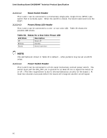
Technical Reference Table 30. 40-Pin LVDS Connector Pin Signal Name Pin 1 ODD_Lane3_P 21 2 ODD_Lane3_N 22 3 ODD_Lane2_P 23 4 ODD_Lane2_N 24 5 ODD_Lane1_P 25 6 ODD_Lane1_N 26 7 ODD_Lane0_P 27 8 ODD_Lane0_N 28 9 EVEN_Lane3_P 29 10 EVEN_Lane3_N 30 11 EVEN_Lane2_P 31 12 EVEN_Lane2_N 32 13 EVEN_Lane1_P 33 14 EVEN_Lane1_N 34 15 EVEN_Lane0_P 35 16 EVEN_Lane0_N 36 17 EDID_GND 37 18 LCD_VCC 38 19 LCD_VCC 39 20 LCD_VCC 40 Signal Name N/C EDID_3.3 V LCD_GND LCD_GND LCD_GND ODD_CLK_P ODD_CLK_N BKLT_GND BKLT_GND BKLT_GND EDID_CLK BKLT_ENABLE BKLT_PWM_DIM EVEN_CLK_P EVEN_CLK_N BKLT_PWR BKLT_PWR BKLT_PWR N/C EDID_DATA NOTE Single-channel LVDS panels must be wired to the "EVEN" channel of the LVDS connector on initial revisions of the Intel Desktop Board DN2800MT (G23738-600 and earlier), as opposed to the "ODD" channel expected by single-channel LVDS designs. A future motherboard revision (G23738-800 and later) is planned to support singlechannel LVDS connectivity out of the "ODD" channel. Intel recommends that customers planning to use single-channel LVDS panels ensure cable wiring matches the target board revision. 55
-
 1
1 -
2
-
3
-
4
-
5
-
6
-
7
-
8
-
9
-
10
-
11
-
12
-
13
-
14
-
15
-
16
-
17
-
18
-
19
-
20
-
21
-
22
-
23
-
24
-
25
-
26
-
27
-
28
-
29
-
30
-
31
-
32
-
33
-
34
-
35
-
36
-
37
-
38
-
39
-
40
-
41
-
42
-
43
-
44
-
45
-
46
-
47
-
48
-
49
-
 50
50 -
 51
51 -
 52
52 -
 53
53 -
 54
54 -
 55
55 -
 56
56 -
 57
57 -
 58
58 -
 59
59 -
 60
60 -
61
-
62
-
63
-
64
-
65
-
66
-
67
-
68
-
69
-
70
-
71
-
72
-
73
-
74
-
75
-
76
-
77
-
78
-
79
-
80
-
81
-
82
-
83
-
84
-
85
-
86
-
87
-
88
-
89
-
90
-
91
-
92
-
93
-
94
-
95
-
96
-
97
-
98
-
99
-
100
-
101
-
102
-
103
-
104
-
105
-
106
-
107
 |
 |