Intel DN2800MT Technical Product Specification for Intel Desktop Board DN2800M - Page 73
Chassis Design Guideline
 |
View all Intel DN2800MT manuals
Add to My Manuals
Save this manual to your list of manuals |
Page 73 highlights
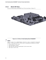
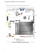
Technical Reference Table 41 provides maximum case temperatures for the components that are sensitive to thermal changes. The operating temperature, current load, or operating frequency could affect case temperatures. Maximum case temperatures are important when considering proper airflow to cool the board. Table 41. Thermal Considerations for Various Components and Subsystems Component Maximum Case Temperature Processor For processor case temperature, see processor datasheets and processor specification updates Intel NM10 Express Chipset Voltage regulator subsystem Serial port transceivers mSATA/PCIe multiplexer SuperIO device Audio codec device LAN subsystem eDP/LVDS subsystem DC-to-DC subsystem USB subsystem SO-DIMMs (typical) 115 oC 85 oC 85 oC 85 oC 85 oC 85 oC 85 oC 85 oC 85 oC 85 oC 85 oC 2.7.1 Chassis Design Guideline The pin fin heatsink design used on this board will be able to dissipate up to 6.5 W of processor power in most fanless chassis. This board is targeted for 1-3 liters volumetric or larger in slim desktop or All-in-One configurations, vertically or horizontally oriented thin mini-ITX chassis For best thermal performance, it is recommended to have a system fan providing reasonable airflow directly over all the major components on the board. The pin fin heatsink is designed to have the best thermal performance when airflow direction is parallel to the heatsink fins. It is highly recommended that cables and chassis hardware do not block the direction of the airflow towards the processor, memory or other components. The processor on the board will generate the highest amount of heat, leading to high ambient temperature within the chassis. If available, the system fan should be located near the board region in order to effectively regulate airflow (see Figure 24). A system fan located further away from the board region, i.e., at the optical disk drive or hard disk drive region, will be less effective in controlling the local ambient temperature. Regardless of where the system fan is located, maximum inner chassis temperature must not exceed the maximum operating temperature as defined in the environmental specifications in Section 2.9. Chassis inlet vents should also provide adequate openings for airflow to pass through. By using the built-in pin fin heatsink, most chassis with a system fan should have inner chassis temperature safely below the specified limit. 73
-
 1
1 -
2
-
3
-
4
-
5
-
6
-
7
-
8
-
9
-
10
-
11
-
12
-
13
-
14
-
15
-
16
-
17
-
18
-
19
-
20
-
21
-
22
-
23
-
24
-
25
-
26
-
27
-
28
-
29
-
30
-
31
-
32
-
33
-
34
-
35
-
36
-
37
-
38
-
39
-
40
-
41
-
42
-
43
-
44
-
45
-
46
-
47
-
48
-
49
-
50
-
51
-
52
-
53
-
54
-
55
-
56
-
57
-
58
-
59
-
60
-
61
-
62
-
63
-
64
-
65
-
66
-
67
-
 68
68 -
 69
69 -
 70
70 -
 71
71 -
 72
72 -
 73
73 -
 74
74 -
 75
75 -
 76
76 -
 77
77 -
 78
78 -
79
-
80
-
81
-
82
-
83
-
84
-
85
-
86
-
87
-
88
-
89
-
90
-
91
-
92
-
93
-
94
-
95
-
96
-
97
-
98
-
99
-
100
-
101
-
102
-
103
-
104
-
105
-
106
-
107
 |
 |