Intel DN2800MT Technical Product Specification for Intel Desktop Board DN2800M - Page 71
Thermal Considerations - case
 |
View all Intel DN2800MT manuals
Add to My Manuals
Save this manual to your list of manuals |
Page 71 highlights
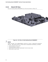
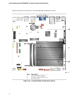
Technical Reference 2.6.2 Fan Header Current Capability Table 40 lists the current capability of the fan header. Table 40. Fan Header Current Capability Fan Header Maximum Available Current System fan 1.5 A 2.6.3 PCI Express* Add-in Card Considerations The motherboard is designed to provide up to 10 W to the PCI Express x1 slot. The total power consumption from add-in boards on this slot must not exceed this rating. 2.7 Thermal Considerations CAUTION For fanless operation, a chassis with adequate venting holes to enable fanless cooling of all board- and system-level components is required. CAUTION Failure to ensure appropriate airflow may result in reduced performance of both the processor and/or voltage regulator or, in some instances, damage to the board. All responsibility for determining the adequacy of any thermal or system design remains solely with the system integrator. Intel makes no warranties or representations that merely following the instructions presented in this document will result in a system with adequate thermal performance. CAUTION Ensure that the ambient and especially the internal chassis temperatures do not exceed the board's maximum operating temperatures. Failure to do so could cause components to exceed their maximum case temperature and malfunction. For information about the maximum operating temperatures, see the environmental specifications in Section 2.9. CAUTION Ensure that proper airflow is maintained in the processor voltage regulator circuit. Failure to do so may result in damage to the voltage regulator circuit. The processor voltage regulator area (shown in Figure 23) can reach a temperature of up to 85 oC in an open chassis. 71
-
 1
1 -
2
-
3
-
4
-
5
-
6
-
7
-
8
-
9
-
10
-
11
-
12
-
13
-
14
-
15
-
16
-
17
-
18
-
19
-
20
-
21
-
22
-
23
-
24
-
25
-
26
-
27
-
28
-
29
-
30
-
31
-
32
-
33
-
34
-
35
-
36
-
37
-
38
-
39
-
40
-
41
-
42
-
43
-
44
-
45
-
46
-
47
-
48
-
49
-
50
-
51
-
52
-
53
-
54
-
55
-
56
-
57
-
58
-
59
-
60
-
61
-
62
-
63
-
64
-
65
-
 66
66 -
 67
67 -
 68
68 -
 69
69 -
 70
70 -
 71
71 -
 72
72 -
 73
73 -
 74
74 -
 75
75 -
 76
76 -
77
-
78
-
79
-
80
-
81
-
82
-
83
-
84
-
85
-
86
-
87
-
88
-
89
-
90
-
91
-
92
-
93
-
94
-
95
-
96
-
97
-
98
-
99
-
100
-
101
-
102
-
103
-
104
-
105
-
106
-
107
 |
 |
