Intel DN2800MT Technical Product Specification for Intel Desktop Board DN2800M - Page 58
Add-in Card Connectors, 2.3.3, Power Supply Connectors
 |
View all Intel DN2800MT manuals
Add to My Manuals
Save this manual to your list of manuals |
Page 58 highlights
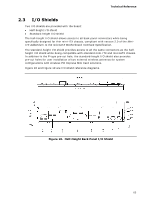
Intel Desktop Board DN2800MT Technical Product Specification Table 33. PCI Express Full-/Half-Mini Card Connector (continued) Pin Signal Name Additional Signal Name 39 +3.3 V aux (mSATA) 3.3 V 40 GND 41 +3.3 V aux 42 LED_WWAN# (mSATA) 3.3 V 43 Reserved NC (mSATA indicator) 44 LED_WLAN# 45 Reserved (mSATA) Vendor 46 LED_WPAN# 47 Reserved (mSATA) Vendor 48 +1.5V 49 Reserved 50 GND 51 Reserved (mSATA) DA/DSS (mSATA) Presence Detection 52 +3.3 V aux 2.2.3.2 Add-in Card Connectors The board has the following add-in card connectors: • One PCI Express 1.0a x1 connector. The x1 interface supports simultaneous transfer speeds up to 250 MB/s of peak bandwidth per lane, per direction, for up to 500 MB/s concurrent and bi-directional bandwidth. • One PCI Express Half-Mini Card slot • One PCI Express Full-/Half-Mini Card slot (removable stand-offs in full-length keep out zone allows repurposing of Full-Mini Card slot into Half-Mini Card slot) 2.2.3.3 Power Supply Connectors The board supports wide-range voltage input by either of the following power supply types: • External Power Supply - the board can be powered with an 8 - 19 VDC external power supply though the DC jack on the back panel. This connector accepts dualbarrel plugs with an inner diameter (ID) of 2.5 mm and an outer diameter (OD) of 5.5 mm, where the inner contact is +8 (±10%) through +19 (±10%) VDC and the shell is GND. The maximum current rating for this connector is 8 A. • Internal Power Supply - the board can alternatively be powered via the internal 1 x 2 power connector, where pin 1 is GND and pin 2 is +8 (±10%) through +19 (±10%) VDC. The maximum current rating for this connector is 10 A. Table 34. Internal Power Supply Connector Pinout Pin Signal Name 1 Ground 2 DC input: +8 (±10%) through +19 (±10%) VDC 58
-
 1
1 -
2
-
3
-
4
-
5
-
6
-
7
-
8
-
9
-
10
-
11
-
12
-
13
-
14
-
15
-
16
-
17
-
18
-
19
-
20
-
21
-
22
-
23
-
24
-
25
-
26
-
27
-
28
-
29
-
30
-
31
-
32
-
33
-
34
-
35
-
36
-
37
-
38
-
39
-
40
-
41
-
42
-
43
-
44
-
45
-
46
-
47
-
48
-
49
-
50
-
51
-
52
-
 53
53 -
 54
54 -
 55
55 -
 56
56 -
 57
57 -
 58
58 -
 59
59 -
 60
60 -
 61
61 -
 62
62 -
 63
63 -
64
-
65
-
66
-
67
-
68
-
69
-
70
-
71
-
72
-
73
-
74
-
75
-
76
-
77
-
78
-
79
-
80
-
81
-
82
-
83
-
84
-
85
-
86
-
87
-
88
-
89
-
90
-
91
-
92
-
93
-
94
-
95
-
96
-
97
-
98
-
99
-
100
-
101
-
102
-
103
-
104
-
105
-
106
-
107
 |
 |
