Intel SE7210TP1-E User Guide
Intel SE7210TP1-E - Socket 478 ATX Server Motherboard Manual
 |
UPC - 810884006803
View all Intel SE7210TP1-E manuals
Add to My Manuals
Save this manual to your list of manuals |
Intel SE7210TP1-E manual content summary:
- Intel SE7210TP1-E | User Guide - Page 1
Intel® Entry Server Board SE7210TP1-E User Guide Order Number: C49109-002 - Intel SE7210TP1-E | User Guide - Page 2
product could create a situation where personal injury or death may occur. Intel may make changes to specifications and product descriptions at any time, without notice. Intel server boards contain a number of high-density VLSI and power delivery components that need adequate airflow for cooling - Intel SE7210TP1-E | User Guide - Page 3
you may need, troubleshooting information, and instructions on how to add and replace components on the Intel Entry Server Board SE7210TP1-E. For the latest version of this manual, refer to http://www.support.intel.com/support/motherboards/server/SE7210TP1-E. Manual Organization Chapter 1 provides - Intel SE7210TP1-E | User Guide - Page 4
find the information below: http://www.support.intel.com/support/motherboards/server/SE7210TP1-E/index.htm ƒ In-depth technical information about this product, including BIOS settings and chipset information in the Intel® Server Board SE7210TP1-E Technical Product Specification. ƒ The latest product - Intel SE7210TP1-E | User Guide - Page 5
. Turn off the server and disconnect the power cord, telecommunications systems, networks, and modems attached to the server before opening it. Otherwise, personal injury or equipment damage can result. Electrostatic discharge (ESD) and ESD protection: ESD can damage disk drives, boards, and other - Intel SE7210TP1-E | User Guide - Page 6
.support.intel.com/support/motherboards/server/SE7210TP1E. 上的 Intel Server Boards and Server Chassis Safety Information(《Intel Consignes de sécurité Lisez attention toutes les consignes de sécurité et les mises en garde indiquées dans ce document avant de suivre toute instruction. Consultez Intel - Intel SE7210TP1-E | User Guide - Page 7
...17 2 Server Board Installations and Upgrades 19 Before You Begin ...19 Tools and Supplies Needed 19 Installing and Removing Memory 19 Installing DIMMs...19 Removing DIMMs...20 Installing or Replacing the Processor 21 Installing the Processor 21 Removing the Processor 24 Installing - Intel SE7210TP1-E | User Guide - Page 8
a Server 37 Problems with Network 37 System Boots when Installing PCI Card 38 Problems with Newly Installed Application Software 38 Problems with Application Software that Ran Correctly Earlier 38 Devices are not Recognized under Device Manager (Windows* Operating System).. 39 Hard Drive(s) are - Intel SE7210TP1-E | User Guide - Page 9
Figure 1. Intel® Server Board SE7210TP1-E 11 Figure 2. Intel Server Board SE7210TP1-E Layout 13 Figure 3. Making Connections to the Server Board 14 Figure 4. Configuration Jumper Location 15 Figure 5. Back Panel Connectors 16 Figure 6. Installing Memory 20 Figure 7. Installing the Processor in - Intel SE7210TP1-E | User Guide - Page 10
Contents x - Intel SE7210TP1-E | User Guide - Page 11
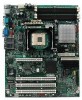
1 support is provided for Serial ATA drives. ƒ The server board SE7210TP1SCSI includes a single channel, Ultra320 SCSI controller: Adaptec* AIC-7901. The Server Board SE7210TP1-E is shown in the following picture. Figure 1. Intel® Server Board SE7210TP1-E Intel Server Board SE7210TP1-E User Guide - Intel SE7210TP1-E | User Guide - Page 12
board SE7210TP1SCSI): Adaptec* AIC-7901 Support for up to six system fans and one processor fan Intel/AMI BIOS with support for: ƒ Advanced Configuration and Power Interface (ACPI) ƒ 8 megabit symmetrical flash memory ƒ Support for SMBIOS continued 12 Intel Server Board SE7210TP1-E User Guide - Intel SE7210TP1-E | User Guide - Page 13
Slot 6, 32/33 GG: NIC 2 (10/100 Mbit) HH: NIC 1 (1 Gbit) II: Video Connector JJ: Serial A Connector KK: Keyboard and Mouse LL: USB Connectors Figure 2. Intel Server Board SE7210TP1-E Layout Intel Server Board SE7210TP1-E User Guide 13 - Intel SE7210TP1-E | User Guide - Page 14
hard drive cage contains one of the front system fans. 12 V BA A B T S R A T Q A 1 0 0 P ON XM WL Serial ATA CD EM F GN H I JU K TP00507 Figure 3. Making Connections to the Server Board A: CPU1 Fan Connector B: +12V CPU Power B Header 14 Intel Server Board SE7210TP1-E User Guide - Intel SE7210TP1-E | User Guide - Page 15
jumpered, the system will attempt to recover the BIOS by loading the BIOS code into the flash device from a floppy disk. This jumper is typically only used when the BIOS has become corrupted. These pins should be jumpered on 13-14 for normal operation. Intel Server Board SE7210TP1-E User Guide 15 - Intel SE7210TP1-E | User Guide - Page 16
LED is on) 100 Mbps connection Network connection in place Transmit/receive activity No network connection Network connection in place Transmit/receive activity 10 Mbps connection (if left LED is on or blinking) 100 Mbps connection 1000 Mbps connection 16 Intel Server Board SE7210TP1-E User Guide - Intel SE7210TP1-E | User Guide - Page 17
DIMMs must be ECC. If both ECC and non-ECC DIMMs are used, ECC will be disabled and will not function. Power Supply A minimum of 450 Watts is required. Your supply must provide a minimum of 1.2 A of 5 V standby current or the board will not boot. Intel Server Board SE7210TP1-E User Guide 17 - Intel SE7210TP1-E | User Guide - Page 18
Server Board Features 18 Intel Server Board SE7210TP1-E User Guide - Intel SE7210TP1-E | User Guide - Page 19
the safety and ESD precautions at the beginning of this book. 2. Turn off all peripheral devices connected to the server. Turn off the server. 3. Disconnect the AC power cord. 4. Remove the chassis cover and locate the DIMM sockets (see Figure 6). Intel Server Board SE7210TP1-E User Guide 19 - Intel SE7210TP1-E | User Guide - Page 20
Server Installations and Upgrades 2B 2A 1B 1A 1 3 2 1 3 Figure 6. Installing Memory TP00518 5. Make sure the clips at either end of removed or disconnected to reach the DIMM sockets. 8. Replace the server's cover and reconnect the AC power cord. 20 Intel Server Board SE7210TP1-E User Guide - Intel SE7210TP1-E | User Guide - Page 21
completely. See letter C. A B C TP00519 Figure 7. Installing the Processor in the Processor Socket ✏ NOTE The bottom of the heat sink may have thermal interface material (TIM) already applied. Be careful not to damage the thermal interface material. Intel Server Board SE7210TP1-E User Guide 21 - Intel SE7210TP1-E | User Guide - Page 22
position, push down firmly to secure the retention mechanism clips, represented by letter "B" in Figure 9. B B B B A A C TP00521 Figure 9. Attaching the Fan Heat Sink Clips to the Processor Socket 22 Intel Server Board SE7210TP1-E User Guide - Intel SE7210TP1-E | User Guide - Page 23
10. TP00522 Figure 10. Attaching the Fan Heat Sink Clips to the Processor Socket 10. Connect the processor fan cable to the processor fan connector. See Figure 11. TP00523 Figure 11. Connecting the Processor Fan Cable to the Processor Fan Connector Intel Server Board SE7210TP1-E User Guide 23 - Intel SE7210TP1-E | User Guide - Page 24
. Discard used batteries according to manufacturer's instructions. ADVARSEL! Lithiumbatteri - Eksplosionsfare ved fejlagtig håndtering. Udskiftning må kun ske med batteri af samme fabrikat og type. Levér det brugte batteri tilbage til leverandøren. 24 Intel Server Board SE7210TP1-E User Guide - Intel SE7210TP1-E | User Guide - Page 25
Turn off all peripheral devices connected to the server. Turn off the server. 3. Disconnect the AC power cord from the server. 4. Remove the server's cover and locate the battery. 5. Insert from its socket. TP00511 Figure 12. Replacing the Battery Intel Server Board SE7210TP1-E User Guide 25 - Intel SE7210TP1-E | User Guide - Page 26
Server Installations and Upgrades 7. Dispose of the battery according to local ordinance. 8. Remove the new lithium battery from its package, it in the battery socket. 9. Close the chassis. 10. Run Setup to restore the configuration settings to the RTC. 26 Intel Server Board SE7210TP1-E User Guide - Intel SE7210TP1-E | User Guide - Page 27
Server Utilities 3 Server Utilities BIOS Setup Table 4. Press F5/F6/+ Enter key is pressed, or the ESC key is pressed, the user is returned to where they were before F10 was pressed without affecting any existing values. Intel Server Board SE7210TP1-E User Guide 27 - Intel SE7210TP1-E | User Guide - Page 28
upgrade. Review also any release notes in the release notes file that accompanies the new version of the BIOS. The release notes may contain critical information regarding jumper settings, specific fixes, or other information to complete the upgrade. 28 Intel Server Board SE7210TP1-E User Guide - Intel SE7210TP1-E | User Guide - Page 29
the parameters back to default values. 9. Re-enter the values you wrote down at the beginning of this process. Press F10 and to exit BIOS Setup and Save Changes. Intel Server Board SE7210TP1-E User Guide 29 - Intel SE7210TP1-E | User Guide - Page 30
the AC power source. 2. Move the recovery jumper at J1D1 from pins 13 and 14 to cover pins 14 and 15. 3. Insert a bootable diskette containing the file AMIBOOT.ROM into the A: diskette drive. 4. Plug the system into the AC power source and power it on. 30 Intel Server Board SE7210TP1-E User Guide - Intel SE7210TP1-E | User Guide - Page 31
power up the system. 5. When the system begins beeping, power it down and disconnect the AC power. 6. Return the CMOS Clear jumper to the original location, covering pins 1 and 2. 7. Close the server chassis, reconnect the AC power and power up the system. Intel Server Board SE7210TP1-E User Guide - Intel SE7210TP1-E | User Guide - Page 32
on add-in boards and peripheral devices correct? To check these settings, refer to the manufacturer's documentation that comes with them. If applicable, ensure that there are no conflicts-for example, two add-in boards sharing the same interrupt. Intel Server Board SE7210TP1-E User Guide 32 - Intel SE7210TP1-E | User Guide - Page 33
: ‰ Does the diskette drive activity light turn on briefly? If not, see "Diskette Drive Activity Light Does Not Light." ‰ If system LEDs are illuminated, see "LED Information" for a description of the light and steps to take to correct the problem. Intel Server Board SE7210TP1-E User Guide 33 - Intel SE7210TP1-E | User Guide - Page 34
according to the system requirements. ‰ Remove the processor(s) and re-seat them. ‰ Make sure the chassis standoffs are installed only below mounting holes. Misplaced standoffs can contact the pins on the bottom of the server board and cause a short. 34 Intel Server Board SE7210TP1-E User Guide - Intel SE7210TP1-E | User Guide - Page 35
and contrast controls properly adjusted on the video monitor? See the manufacturer's documentation. ‰ Are the video monitor's signal and power cables properly installed? ‰ Does this video monitor work correctly if plugged into a different system? Intel Server Board SE7210TP1-E User Guide 35 - Intel SE7210TP1-E | User Guide - Page 36
or DVD-ROM Drive Activity Light Does Not Light Check the following: ‰ Are the CD-ROM/DVD-ROM drive's power and signal cables properly installed? ‰ Are all relevant switches and jumpers on the drive set correctly? ‰ Is the drive properly configured? 36 Intel Server Board SE7210TP1-E User Guide - Intel SE7210TP1-E | User Guide - Page 37
. The add-in adapter stopped working without apparent cause. ‰ Try reseating the adapter first; then try a different slot if necessary. ‰ The network driver files may be corrupt or deleted. Delete and then reinstall the drivers. ‰ Run the diagnostics. Intel Server Board SE7210TP1-E User Guide 37 - Intel SE7210TP1-E | User Guide - Page 38
voltage spike, power outage, or brownout might have occurred, reload the software and try running it again. Symptoms of voltage spikes include a flickering video display, unexpected system reboots, and the system not responding to user commands. 38 Intel Server Board SE7210TP1-E User Guide - Intel SE7210TP1-E | User Guide - Page 39
. ‰ If using a RAID configuration with SCSI or SATA drives, make sure the RAID card is installed correctly. Bootable CD-ROM Is Not Detected Check the following: ‰ Make sure the BIOS is configured to allow the CD-ROM to be the first bootable device. Intel Server Board SE7210TP1-E User Guide 39 - Intel SE7210TP1-E | User Guide - Page 40
blink = non-critical Blinking = Activity. No action required. On = Fault See the POST code table On = Fault On = Fault On = Fault On = 5v standby power on ƒ Off = Power is off (off or S5) ƒ On = Power on or S0) ƒ Slow Blink = Low power state (S1 - S3) 40 Intel Server Board SE7210TP1-E User Guide - Intel SE7210TP1-E | User Guide - Page 41
last boot. If no memory was added or removed, then memory may be bad. No Boot Device Available Off Board Parity Error System did not find a device to boot. A parity error occurred on an off-board card. This error is followed by an address. continued Intel Server Board SE7210TP1-E User Guide 41 - Intel SE7210TP1-E | User Guide - Page 42
11 Invalid BIOS (such as, POST module not found) BIOS Recovery Beep Codes Table 7. BIOS Recovery Beep Codes Number of Beeps Reason 1 One long beep - video is active. 1-2 One long beep and two short beeps: Insert the BIOS recovery diskette. 42 Intel Server Board SE7210TP1-E User Guide - Intel SE7210TP1-E | User Guide - Page 43
update, where video is not available for text messages to be displayed, speaker beeps are necessary to inform the user of errors. For beep codes associated with a Bootblock update refer to the Intel® Server Board SE7210TP1-E Technical Product Specification. Intel Server Board SE7210TP1-E User Guide - Intel SE7210TP1-E | User Guide - Page 44
(Class A) Radiated & Conducted Emissions (Korea) ƒ BSMI CNS13438 (Class A) Radiated & Conducted Emissions (Taiwan) ƒ GOST R 29216-91 (Class A) Radiated & Conducted Emissions (Russia) ƒ GOST R 50628-95 (Immunity) (Russia) Intel Server Board SE7210TP1-E User Guide 44 - Intel SE7210TP1-E | User Guide - Page 45
C-Tick Mark BSMI DOC Marking BSMI EMC Warning RRL MIC Mark Electromagnetic Compatibility Notices FCC (USA) This device complies with Part 15 of the FCC product, contact: Intel Corporation 5200 N.E. Elam Young Parkway Hillsboro, OR 97124 1-800-628-8686 Intel Server Board SE7210TP1-E User Guide 45 - Intel SE7210TP1-E | User Guide - Page 46
radiate radio frequency energy and, if not installed and used in accordance with the instructions, may cause harmful interference to radio communications. However, there is no guarantee that been marked with the BSMI DOC mark to illustrate compliance. 46 Intel Server Board SE7210TP1-E User Guide - Intel SE7210TP1-E | User Guide - Page 47
Recipient: Intel 4. Date of Manufacturer: Marked on Product 5. Manufacturer / Nation : Intel Australia / New Zealand This product has been tested and complies with AS/NZS 3548. The product has been marked with the C-Tick mark to illustrate compliance. Intel Server Board SE7210TP1-E User Guide 47 - Intel SE7210TP1-E | User Guide - Page 48
(via AT&T) 008-11, 800-628-8686 (via AT&T) 0-800-50000, 800-628-8686 (via AT&T) 000-410, 800-628-8686 (via AT&T) For an updated support contact list, see http://www.support.intel.com/support/motherboards/server/SE7210TP1-E Intel Server Board SE7210TP1-E User Guide 48 - Intel SE7210TP1-E | User Guide - Page 49
ˆ Intel SC5200 Base Redundant Power ˆ Intel SC5250-E ˆ Other (Vendor / Model): DIMM Configuration DIMM1A MB: DIMM1A Vendor/part number: DIMM1B MB: DIMM1B Vendor/part number: DIMM2A MB: DIMM2A Vendor/part number: DIMM2B MB: DIMM2B Vendor/part number: 49 Intel Server Board SE7210TP1-E User Guide - Intel SE7210TP1-E | User Guide - Page 50
Service Driver Revision IRQ # I/O Base Address FW Rev# Hard Drive Information: ˆ IDE # of drives installed: Make/Model/Firmware Revision ˆ SCSI # of drives installed: Make/Model/Firmware Revision ˆ SATA # of drives installed: Make/Model/Firmware Revision Intel Server Board SE7210TP1-E User Guide - Intel SE7210TP1-E | User Guide - Page 51
Form Complete Problem Description In the space below, provide a complete description of the steps used to reproduce the problem or a complete description of where the problem can be found. Please also include any details on troubleshooting already done. 51 Intel Server Board SE7210TP1-E User Guide
-
 1
1 -
 2
2 -
 3
3 -
 4
4 -
 5
5 -
 6
6 -
 7
7 -
8
-
9
-
10
-
11
-
12
-
13
-
14
-
15
-
16
-
17
-
18
-
19
-
20
-
21
-
22
-
23
-
24
-
25
-
26
-
27
-
28
-
29
-
30
-
31
-
32
-
33
-
34
-
35
-
36
-
37
-
38
-
39
-
40
-
41
-
42
-
43
-
44
-
45
-
46
-
47
-
48
-
49
-
50
-
51
 |
 |

Intel
®
Entry Server Board SE7210TP1-E
User Guide
Order Number:
C49109-002