Intel SE7210TP1-E User Guide - Page 14
Internal Component Connections, Intel Server Board SE7210TP1-E User Guide
 |
UPC - 810884006803
View all Intel SE7210TP1-E manuals
Add to My Manuals
Save this manual to your list of manuals |
Page 14 highlights
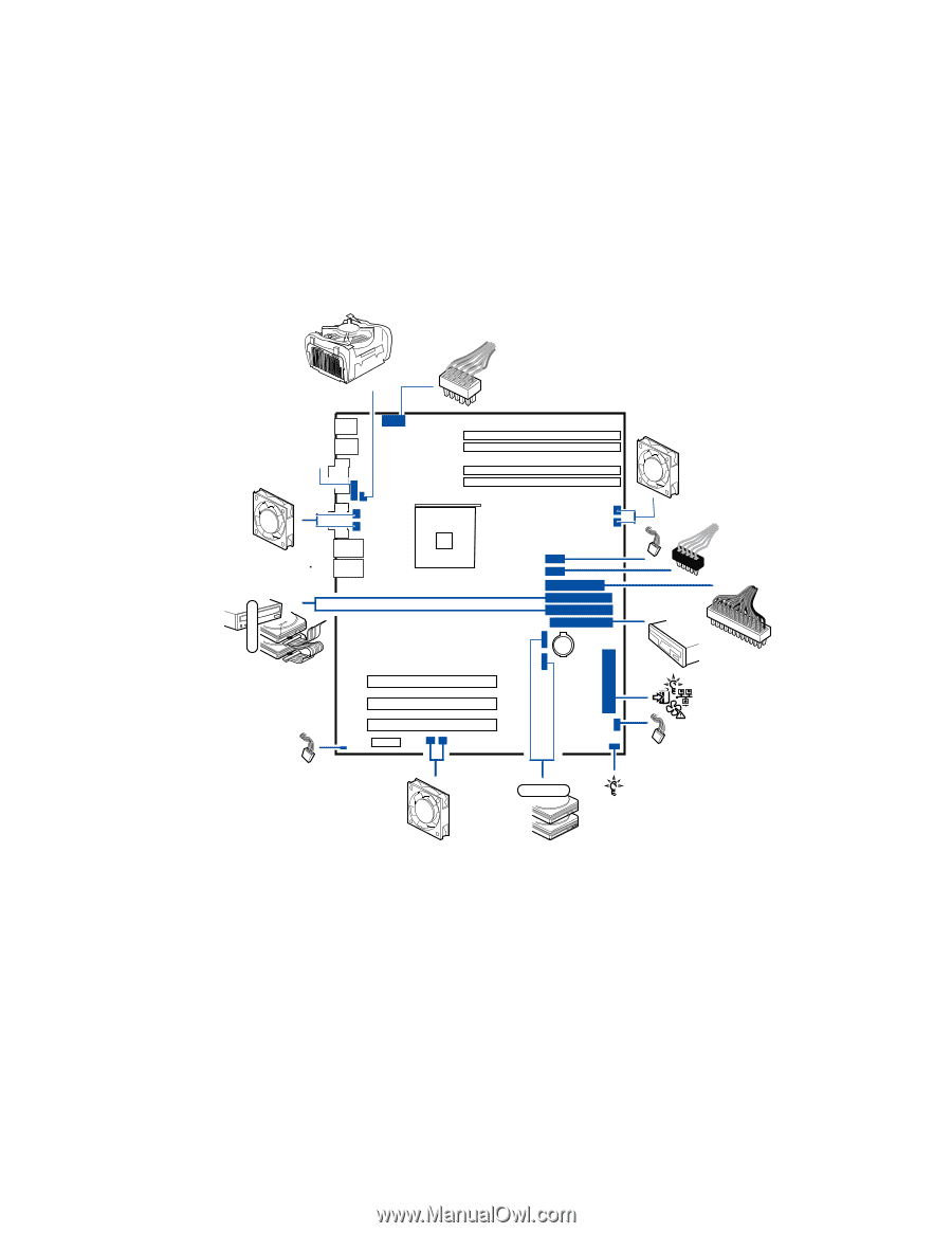
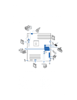
Server Board Features Internal Component Connections The connections you make depend on the chassis you are installing the board into and the components you are installing. You may not need to make all of the connections shown in Figure 3. If your Server Board SE7210TP1-E is installed into the Server Chassis SC5250-E, make sure the hard drive cage is installed before making your connections. This is necessary because the hard drive cage contains one of the front system fans. 12 V BA A B T S R A T Q A 1 0 0 P ON XM WL Serial ATA CD EM F GN H I JU K TP00507 Figure 3. Making Connections to the Server Board A: CPU1 Fan Connector B: +12V CPU Power Connector C: System Fan Header 2 D: System Fan Header 1 E: Front USB Header F: Auxiliary Power Connector G: Main Power Connector H: Floppy Connector I: Front Panel Connector J: Hot-swap Backplane Headers K: HDD LED L: SATA Port A1 M: SATA Port A2 N: System Fan Header 6 O: System Fan Header 5 P: Chassis Intrusion Header Q: IDE Connectors R: System Fan Header 4 S: System Fan Header 3 T: Serial B Header 14 Intel Server Board SE7210TP1-E User Guide
-
 1
1 -
2
-
3
-
4
-
5
-
6
-
7
-
8
-
 9
9 -
 10
10 -
 11
11 -
 12
12 -
 13
13 -
 14
14 -
 15
15 -
 16
16 -
 17
17 -
 18
18 -
 19
19 -
20
-
21
-
22
-
23
-
24
-
25
-
26
-
27
-
28
-
29
-
30
-
31
-
32
-
33
-
34
-
35
-
36
-
37
-
38
-
39
-
40
-
41
-
42
-
43
-
44
-
45
-
46
-
47
-
48
-
49
-
50
-
51
 |
 |