Invacare 3GTQSPBASE Owners Manual - Page 100
NF Batteries in Single Battery Box
 |
View all Invacare 3GTQSPBASE manuals
Add to My Manuals
Save this manual to your list of manuals |
Page 100 highlights
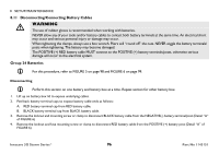
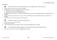
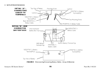
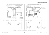
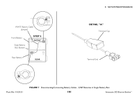
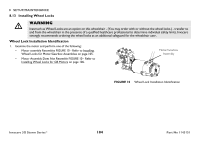
8 SETUP/MAINTENANCE 22NF Batteries in Single Battery Box For this procedure, refer to FIGURE 7 on page 101 and FIGURE 8 on page 102. Note polarity of white battery cable (jumper) battery terminal ends. Disconnecting 1. Remove battery terminal cap(s) from battery terminal(s) ends. Refer to Detail A" in FIGURE 7 on page 101. 2. Disconnect WHITE battery cable (jumper) NEGATIVE (-) terminal end from NEGATIVE (-) battery terminal/post of front battery and disconnect POSITIVE (+) terminal end from POSITIVE (+) battery terminal/post of rear battery. 3. Disconnect NEGATIVE (-) BLACK battery cable of the battery box top from NEGATIVE (-) battery terminal/post of rear battery. 4. Disconnect POSITIVE (+) RED battery cable on battery box top from POSITIVE (+) battery terminal/post of front battery. Connecting 1. Remove battery terminal cap(s) from battery terminal(s) ends. Refer to Detail "A" in FIGURE 7 on page 101. 2. Connect WHITE battery cable (jumper) NEGATIVE (-) terminal end to NEGATIVE (-) battery terminal/post of front battery and connect POSITIVE (+) terminal end to POSITIVE (+) battery terminal/post of rear battery. 3. Place battery top upside down on top of rear battery. 4. Connect NEGATIVE (-) BLACK battery cable of the battery box top to NEGATIVE (-) battery terminal/post of rear battery. 5. Position battery box top right side up and rotate outward toward right to expose POSITIVE (+) battery terminal/post of front battery. 6. Connect POSITIVE (+) RED battery cable on battery box top to POSITIVE (+) battery terminal/post of front battery. 7. Replace battery terminal cap(s) onto battery cable terminal end(s). 8. Rotate top toward left into position. Secure in place. 9. Install the battery box into the wheelchair. Refer to Removing/Installing the 22NF Battery Box on page 92. New batteries MUST be fully charged before using, otherwise the life of the batteries will be reduced 10. If necessary, charge the battery(ies). Refer to Charging Batteries on page 58. Invacare 3G Storm Series® 100 Part No 1143151
-
 1
1 -
2
-
3
-
4
-
5
-
6
-
7
-
8
-
9
-
10
-
11
-
12
-
13
-
14
-
15
-
16
-
17
-
18
-
19
-
20
-
21
-
22
-
23
-
24
-
25
-
26
-
27
-
28
-
29
-
30
-
31
-
32
-
33
-
34
-
35
-
36
-
37
-
38
-
39
-
40
-
41
-
42
-
43
-
44
-
45
-
46
-
47
-
48
-
49
-
50
-
51
-
52
-
53
-
54
-
55
-
56
-
57
-
58
-
59
-
60
-
61
-
62
-
63
-
64
-
65
-
66
-
67
-
68
-
69
-
70
-
71
-
72
-
73
-
74
-
75
-
76
-
77
-
78
-
79
-
80
-
81
-
82
-
83
-
84
-
85
-
86
-
87
-
88
-
89
-
90
-
91
-
92
-
93
-
94
-
 95
95 -
 96
96 -
 97
97 -
 98
98 -
 99
99 -
 100
100 -
 101
101 -
 102
102 -
 103
103 -
 104
104 -
 105
105 -
106
-
107
-
108
-
109
-
110
-
111
-
112
-
113
-
114
-
115
-
116
-
117
-
118
-
119
-
120
 |
 |