Invacare 3GTQSPBASE Owners Manual - Page 87
Lock Levers
 |
View all Invacare 3GTQSPBASE manuals
Add to My Manuals
Save this manual to your list of manuals |
Page 87 highlights
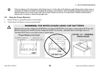
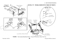
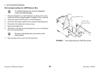
8 SETUP/MAINTENANCE 3. Wheelchairs with TRRO or TRBKTS Only - Perform the following steps: A. Remove the three bolts and washers that secure the front battery retainer bracket (Detail "A"). B. Remove the three short hex screws that secure the top battery retainer bracket to the lower battery retainer bracket. C. Remove the four long hex screws and washers that secure the top battery retainer bracket to the rear of the wheelchair frame (Detail "B"). D. Remove the top battery retainer bracket. E. Remove the lower battery retainer bracket. 4. Rotate the levers of the battery retainer assembly to the unlocked position. 5. Lift battery retainer assembly up off the mounting screws that secure the shocks to the base frame. For GB motors, ensure that the motor lock levers are in the engaged (drive) position. Refer to Disengaging/Engaging Motor Lock Levers on page 61. 6. Slide one connector battery box along the sub-frame and remove from the wheelchair. 7. Slide the two connector battery box along the sub-frame and remove from the wheelchair. Installing 1. Place the wheelchair in a well ventilated area where work can be performed without risking damage to carpeting or floor covering. 2. Verify the joystick On/Off switch is in the Off position. 3. Secure the battery box carrying strap to the lid of the two connector battery box. 4. Place two connector battery box onto the battery sub-frame assembly with guide pins facing the inside of the wheelchair. 5. Slide the two connector battery box along the sub-frame until its guide pins are engaged in the sub-frame connector. Visually inspect to ensure the connection is properly made. Connectors MUST be fully engaged. Make certain that the battery box carrying strap is positioned on top of the battery box and will not interfere with the one connector battery box guide pins when engaging the connector on the one battery box lid. 6. Secure the battery box carrying strap to the lid of the one connector battery box. 7. Place one connector battery box onto battery sub-frame. 8. Slide one connector battery box along the sub-frame until its guide pins are engaged in the connector of the two connector battery box. Part No 1143151 87 Invacare 3G Storm Series®
-
 1
1 -
2
-
3
-
4
-
5
-
6
-
7
-
8
-
9
-
10
-
11
-
12
-
13
-
14
-
15
-
16
-
17
-
18
-
19
-
20
-
21
-
22
-
23
-
24
-
25
-
26
-
27
-
28
-
29
-
30
-
31
-
32
-
33
-
34
-
35
-
36
-
37
-
38
-
39
-
40
-
41
-
42
-
43
-
44
-
45
-
46
-
47
-
48
-
49
-
50
-
51
-
52
-
53
-
54
-
55
-
56
-
57
-
58
-
59
-
60
-
61
-
62
-
63
-
64
-
65
-
66
-
67
-
68
-
69
-
70
-
71
-
72
-
73
-
74
-
75
-
76
-
77
-
78
-
79
-
80
-
81
-
 82
82 -
 83
83 -
 84
84 -
 85
85 -
 86
86 -
 87
87 -
 88
88 -
 89
89 -
 90
90 -
 91
91 -
 92
92 -
93
-
94
-
95
-
96
-
97
-
98
-
99
-
100
-
101
-
102
-
103
-
104
-
105
-
106
-
107
-
108
-
109
-
110
-
111
-
112
-
113
-
114
-
115
-
116
-
117
-
118
-
119
-
120
 |
 |