Invacare 3GTQSPBASE Owners Manual - Page 107
Adjusting Wheel Locks
 |
View all Invacare 3GTQSPBASE manuals
Add to My Manuals
Save this manual to your list of manuals |
Page 107 highlights
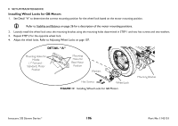
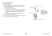
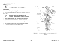
8.14 Adjusting Wheel Locks 1. Make sure wheel lock is disengaged from drive wheel. 2. Measure distance between the Wheel Lock Shoe and the Drive Wheel. 3. Loosen the two hex screws securing the wheel lock to the mounting bracket. 4. Slide the wheel lock along the slots until the measurement is between 5/32 and 5/16-inches. Securely tighten mounting screws. 5. Repeat STEPS 1-3 for the opposite wheel lock. 6. Disengage motor locks. Refer to Disengaging/Engaging Motor Lock Levers on page 61. 7. Engage the wheel locks and push against the wheelchair to determine if the wheel locks engage the drive wheels enough to hold the wheelchair. 8. Repeat STEPS 2-7 until the wheel locks engage the drive wheels enough to hold the wheelchair. 9. Engage motor locks. Refer to Disengaging/Engaging Motor Lock Levers on page 61. 8 SETUP/MAINTENANCE Drive Wheel Wheel Lock Mounting Bracket Wheel Lock Wheel Lock Shoe 5/32 to 5/16 - inch Gap Illustration depicts wheel lock for motor/gearbox assembly. FIGURE 13 8.14Adjusting Wheel Locks Part No 1143151 107 Invacare 3G Storm Series®
-
 1
1 -
2
-
3
-
4
-
5
-
6
-
7
-
8
-
9
-
10
-
11
-
12
-
13
-
14
-
15
-
16
-
17
-
18
-
19
-
20
-
21
-
22
-
23
-
24
-
25
-
26
-
27
-
28
-
29
-
30
-
31
-
32
-
33
-
34
-
35
-
36
-
37
-
38
-
39
-
40
-
41
-
42
-
43
-
44
-
45
-
46
-
47
-
48
-
49
-
50
-
51
-
52
-
53
-
54
-
55
-
56
-
57
-
58
-
59
-
60
-
61
-
62
-
63
-
64
-
65
-
66
-
67
-
68
-
69
-
70
-
71
-
72
-
73
-
74
-
75
-
76
-
77
-
78
-
79
-
80
-
81
-
82
-
83
-
84
-
85
-
86
-
87
-
88
-
89
-
90
-
91
-
92
-
93
-
94
-
95
-
96
-
97
-
98
-
99
-
100
-
101
-
 102
102 -
 103
103 -
 104
104 -
 105
105 -
 106
106 -
 107
107 -
 108
108 -
 109
109 -
 110
110 -
 111
111 -
 112
112 -
113
-
114
-
115
-
116
-
117
-
118
-
119
-
120
 |
 |
