Invacare 3GTQSPBASE Owners Manual - Page 106
Installing Wheel Locks for GB Motors, DETAIL
 |
View all Invacare 3GTQSPBASE manuals
Add to My Manuals
Save this manual to your list of manuals |
Page 106 highlights
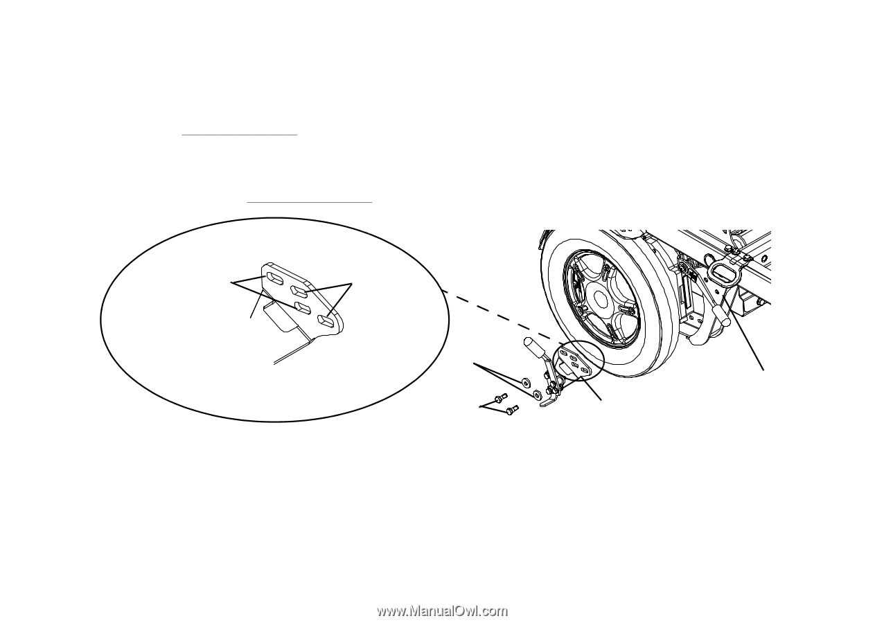
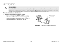
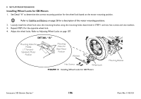
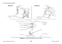
8 SETUP/MAINTENANCE Installing Wheel Locks for GB Motors 1. See Detail "A" to determine the correct mounting position for the wheel lock based on the motor mounting position. Refer to Stability and Balance on page 26 for a description of the motor mounting positions. 2. Loosely install the wheel lock onto the mounting bracket using the mounting holes determined in STEP 1 and two hex screws and two washers. 3. Repeat STEP 2 for the opposite wheel lock. 4. Adjust the wheel locks. Refer to Adjusting Wheel Locks on page 107. DETAIL "A" Mounting Holes for Middle (1" Forward Standard) Motor Position Mounting Holes for Rear Motor Position Washers Hex Screws Wheel Lock FIGURE 12 Installing Wheel Locks for GB Motors Mounting Bracket Invacare 3G Storm Series® 106 Part No 1143151
-
 1
1 -
2
-
3
-
4
-
5
-
6
-
7
-
8
-
9
-
10
-
11
-
12
-
13
-
14
-
15
-
16
-
17
-
18
-
19
-
20
-
21
-
22
-
23
-
24
-
25
-
26
-
27
-
28
-
29
-
30
-
31
-
32
-
33
-
34
-
35
-
36
-
37
-
38
-
39
-
40
-
41
-
42
-
43
-
44
-
45
-
46
-
47
-
48
-
49
-
50
-
51
-
52
-
53
-
54
-
55
-
56
-
57
-
58
-
59
-
60
-
61
-
62
-
63
-
64
-
65
-
66
-
67
-
68
-
69
-
70
-
71
-
72
-
73
-
74
-
75
-
76
-
77
-
78
-
79
-
80
-
81
-
82
-
83
-
84
-
85
-
86
-
87
-
88
-
89
-
90
-
91
-
92
-
93
-
94
-
95
-
96
-
97
-
98
-
99
-
100
-
 101
101 -
 102
102 -
 103
103 -
 104
104 -
 105
105 -
 106
106 -
 107
107 -
 108
108 -
 109
109 -
 110
110 -
 111
111 -
112
-
113
-
114
-
115
-
116
-
117
-
118
-
119
-
120
 |
 |