Invacare TDXSR-CG-HD Owners Manual
Invacare TDXSR-CG-HD Manual
 |
View all Invacare TDXSR-CG-HD manuals
Add to My Manuals
Save this manual to your list of manuals |
Invacare TDXSR-CG-HD manual content summary:
- Invacare TDXSR-CG-HD | Owners Manual - Page 1
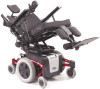
Invacare® TDX®SP, TDX SR Power Wheelchair Base User Manual EN This manual MUST be given to the user of the product. BEFORE using this product, read this manual and save for future reference. - Invacare TDXSR-CG-HD | Owners Manual - Page 2
or modification in whole or in part is prohibited without prior written permission from Invacare. Trademarks are identified by ™ and ®. All trademarks are owned by or licensed to Invacare Corporation or its subsidiaries unless otherwise noted. Invacare® TDX®SP, TDX SR 2 Part No 1143190 - Invacare TDXSR-CG-HD | Owners Manual - Page 3
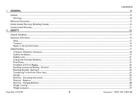
...13 Transport...14 Repair or Service Information ...16 Safety/Handling ...17 A Note to Wheelchair Assistants...18 Stability and Instructions...27 Electrical - Batteries ...27 Electrical - Charging Batteries...28 Weight Training...29 Weight Limitation ...29 Part No 1143190 3 Invacare® TDX®SP, TDX - Invacare TDXSR-CG-HD | Owners Manual - Page 4
Drive the Wheelchair...41 SPJ+, MK6i SPJ+ w/PSS and MK6i SPJ+ w/ACC Joystick Switches and Indicators ...43 On/Off Button ...44 Speedometer...44 Speed Control Buttons...44 Joystick ...45 Charger/Programming Input...45 Information Gauge Display ...45 Service Indicator ...45 Invacare® TDX®SP, TDX SR - Invacare TDXSR-CG-HD | Owners Manual - Page 5
...55 Charging Batteries ...56 Description and Use of Battery Chargers ...57 Disengaging/Engaging Motor Lock Levers ...59 Disengaging/Engaging the Motor Lock Levers - TDX SP...59 Disengaging/Engaging the Motor Lock Levers - TDX SR ...60 Disengaging/Engaging the Wheel locks ...61 Engaging - Invacare TDXSR-CG-HD | Owners Manual - Page 6
...76 Service Inspection Wheelchair ...82 Removing the Front Shroud/Battery Retention Bracket and Rear Shroud...82 Removing the Batteries from Wheelchair ...85 Installing Batteries into Wheelchair ...86 Installing the Front Shroud/Battery Retention Bracket and Rear Shroud ...88 Invacare® TDX®SP, TDX - Invacare TDXSR-CG-HD | Owners Manual - Page 7
ASBA Seats ...95 Van Seats...96 Disconnecting/Connecting the Joysticks ...97 SPJ+ Joysticks ...97 MPJ+ Joysticks...98 8 TROUBLESHOOTING 99 Driving Performance ...99 SPJ+, SPJ+ w/PSS or SPJ+ w/ACC Joysticks...99 Checking Battery Charge Level ...105 Part No 1143190 7 Invacare® TDX®SP, TDX SR - Invacare TDXSR-CG-HD | Owners Manual - Page 8
1 General 1.1 Symbols Warnings Signal words are used in this manual and apply to hazards or unsafe practices which could result in personal it is not avoided. Gives useful tips, recommendations and information for efficient, trouble-free use. Invacare® TDX®SP, TDX SR 8 Part No 1143190 - Invacare TDXSR-CG-HD | Owners Manual - Page 9
are referenced in this manual. MK6i™ Electronics Programming Guide Adjustable ASBA Owner's Manual Van Seat Owner's Manual Formula™ CG Seating System Adjustable ASBA Service Manual MANUAL 1 GENERAL PART NUMBER 1141471 1143192 1143195 1143155 1143238 Part No 1143190 9 Invacare® TDX®SP, TDX SR - Invacare TDXSR-CG-HD | Owners Manual - Page 10
SOLELY DETERMINED BY INVACARE. THE WARRANTY SHALL NOT APPLY TO PROBLEMS ARISING FROM NORMAL WEAR AND TEAR OR FAILURE TO ADHERE TO THE PRODUCT INSTRUCTIONS. A CHANGE IN OPERATING NOISE, PARTICULARLY RELATIVE TO MOTORS AND GEARBOXES DOES NOT CONSTITUTE A FAILURE OR DEFECT AND WILL NOT BE REPAIRED; ALL - Invacare TDXSR-CG-HD | Owners Manual - Page 11
INVACARE. THE WARRANTY SHALL NOT APPLY TO PROBLEMS ARISING FROM NORMAL WEAR AND TEAR OR FAILURE TO ADHERE TO THE PRODUCT INSTRUCTIONS. A CHANGE IN OPERATING NOISE, PARTICULARLY RELATIVE TO MOTORS AND GEARBOXES DOES NOT CONSTITUTE A FAILURE OR DEFECT AND WILL NOT BE REPAIRED Invacare® TDX®SP, TDX SR - Invacare TDXSR-CG-HD | Owners Manual - Page 12
the type of wheelchair to be used by an individual rests solely with the user and his/ her healthcare professional capable of making such a selection. Invacare highly recommends working with a certified rehab technology supplier and/or a member of NRRTS or RESNA. Invacare® TDX®SP, TDX SR 12 Part - Invacare TDXSR-CG-HD | Owners Manual - Page 13
the specifications entered during the set-up procedure. If the wheelchair does not perform to specifications, turn the wheelchair Off immediately and reenter set-up specifications. Repeat this procedure until the wheelchair performs to specifications. Part No 1143190 13 Invacare® TDX®SP, TDX SR - Invacare TDXSR-CG-HD | Owners Manual - Page 14
. Battery support brackets MUST be installed at all times. Otherwise, the wheelchair will not be WC/19 compliant. Refer to Transport Ready Option (TRRO) on page 64. Refer to Transport Ready Option (TRRO) on page 64 for more information about transporting the wheelchair. Invacare® TDX®SP, TDX SR 14 - Invacare TDXSR-CG-HD | Owners Manual - Page 15
. Extreme caution is advised when it is necessary to move an unoccupied power wheelchair up or down the stairs. Invacare recommends using two assistants and making thorough preparations. Make sure to use ONLY secure, non-detachable parts for hand-hold supports. DO NOT use an escalator to move - Invacare TDXSR-CG-HD | Owners Manual - Page 16
the owner's operator and maintenance manual, (2) the service manual (if applicable) and (3) the seating system's manual (if applicable). if you are unable to understand the warnings, cautions and instructions, contact Invacare technical support before attempting to service or operate this equipment - Invacare TDXSR-CG-HD | Owners Manual - Page 17
wheelchair users often develop skills to deal with daily living activities that may differ from those described in this manual. Invacare IMMEDIATELY. DO NOT leave the power button On when entering or exiting your wheelchair. DO NOT go UP or wheelchair. Part No 1143190 17 Invacare® TDX®SP, TDX SR - Invacare TDXSR-CG-HD | Owners Manual - Page 18
used to move the wheelchair or as lifting supports, as they may be inadvertently released, resulting in possible injury to the user and/or assistant(s). When learning a new assistance technique, have an experienced assistant help you before attempting it alone. Invacare® TDX®SP, TDX SR 18 Part No - Invacare TDXSR-CG-HD | Owners Manual - Page 19
different from other wheelchairs previously used. This power wheelchair has Invacare's SureStep® technology, a feature that provides the wheelchair with optimum traction these conditions may shift the users weight forward resulting in reduced stability. Part No 1143190 19 Invacare® TDX®SP, TDX SR - Invacare TDXSR-CG-HD | Owners Manual - Page 20
proper balance. Your wheelchair has been designed to remain upright and stable during normal daily activities as long as you DO NOT move beyond the center of gravity. DO NOT lean forward out of the wheelchair any further than the length of the armrests. Invacare® TDX®SP, TDX SR 20 Part No - Invacare TDXSR-CG-HD | Owners Manual - Page 21
wheelchair. Always stop before climbing an obstacle. Approach slowly until front anti-tip wheels are approximately 18 inches away from the obstacle. Slowly apply power wheelchair to feel unstable. Bump/Threshold FIGURE 1 Coping with Everyday Obstacles Part No 1143190 21 Invacare® TDX®SP, TDX SR - Invacare TDXSR-CG-HD | Owners Manual - Page 22
beam. A pinch point exist between walking beam/head tube cap and telescoping tube when TDX SP is at the lowest seat to floor height. Pinch point may occur when rotating the footboard Pinch Point Front Caster Front Caster FIGURE 2 Pinch Points Invacare® TDX®SP, TDX SR 22 Part No 1143190 - Invacare TDXSR-CG-HD | Owners Manual - Page 23
while the wheelchair is in motion to ensure proper ground clearance. If necessary, adjust the front rigging height or tilt seat to bending could cause the wheelchair to tip forward onto anti-tippers. Engage motor locks and turn power off before reaching, 1143190 23 Invacare® TDX®SP, TDX SR - Invacare TDXSR-CG-HD | Owners Manual - Page 24
and balance. For this procedure, refer to FIGURE 4. Position wheelchair as close as possible to the desired object. Position the casters power off. Reach back only as far as your arm will extend without changing your sitting position. FIGURE 4 Reaching, Bending - Backward Invacare® TDX®SP, TDX - Invacare TDXSR-CG-HD | Owners Manual - Page 25
the wheelchair power OFF and engage the motor locks/clutches to prevent the wheels from moving before attempting to transfer in or out of the wheelchair. Wheelchair Seat Top View Minimize Gap Distance Wheelchair Seat Seat Seat FIGURE 5 Pinch Points Part No 1143190 25 Invacare® TDX®SP, TDX - Invacare TDXSR-CG-HD | Owners Manual - Page 26
property may result. Invacare has tested its power wheelchairs in accordance with ISO 7176 "Rain Test". This provides the end user or his/her attendant sufficient time to remove his/her power wheelchair from a rain storm and retain wheelchair operation. DO NOT leave power wheelchair in a rain storm - Invacare TDXSR-CG-HD | Owners Manual - Page 27
this manual are based on the use of deep cycle gel cell batteries. Invacare strongly recommends their use as the power source for this unit. Carefully read battery/battery charger information prior to installing, servicing or operating your wheelchair. Part No 1143190 27 Invacare® TDX®SP, TDX SR - Invacare TDXSR-CG-HD | Owners Manual - Page 28
proper procedures. Ensure the pins of the extension cord plug are the same number, size, and shape as those on the charger. DO NOT under any circumstances cut or remove the round grounding plug from the charger AC cable plug or the extension cord plug. Invacare® TDX®SP, TDX SR 28 Part No 1143190 - Invacare TDXSR-CG-HD | Owners Manual - Page 29
weight limit (total combined weight of user and any attachments) of your wheelchair model. DO NOT exceed the limit - otherwise, injury or damage may result. 2.3 Electromagnetic Interference (EMI) From Radio Wave Sources Powered wheelchairs be minimized. Part No 1143190 29 Invacare® TDX®SP, TDX SR - Invacare TDXSR-CG-HD | Owners Manual - Page 30
EMI problems to your powered wheelchair. Powered Wheelchair powered wheelchairs and motorized scooters. FOLLOWING THE WARNINGS LISTED BELOW SHOULD REDUCE THE CHANCE OF UNINTENDED BRAKE RELEASE OR POWERED WHEELCHAIR MOVEMENT WHICH COULD RESULT IN SERIOUS INJURY. Invacare® TDX®SP, TDX - Invacare TDXSR-CG-HD | Owners Manual - Page 31
radios, or turn ON personal communication devices, such as cellular phones, while the powered wheelchair is turned ON; 2) Be aware of nearby transmitters, such as radio or scooter as manufactured by Invacare may adversely affect the EMI immunity levels. Part No 1143190 31 Invacare® TDX®SP, TDX SR - Invacare TDXSR-CG-HD | Owners Manual - Page 32
3 LABEL LOCATIONS 3 Label Locations All Wheelchairs Serial Number Label is located on the right side rear swingarm. Invacare® TDX®SP, TDX SR Located on each 4-pole motor. 32 Weight Capacity Label located here (Base Only) Part No 1143190 - Invacare TDXSR-CG-HD | Owners Manual - Page 33
Wheelchairs with 22NF Batteries 3 LABEL LOCATIONS WARNING 22NF have a cross hole located as shown for proper battery connection. See Owner's Manual. These recommendations MUST be followed otherwise injury and/or damage may occur. P/N front shroud. Part No 1143190 33 Invacare® TDX®SP, TDX SR - Invacare TDXSR-CG-HD | Owners Manual - Page 34
3 LABEL LOCATIONS Wheelchairs with GP24 Batteries Invacare® TDX®SP, TDX SR 34 Part No 1143190 - Invacare TDXSR-CG-HD | Owners Manual - Page 35
Wheelchairs with TRRO Also on opposite side of wheelchair. 3 LABEL LOCATIONS Wheelchairs without TRRO Part No 1143190 Auto style seat positioning strap shown. This label is also on the airline style seat positioning strap. 35 Invacare® TDX®SP, TDX SR - Invacare TDXSR-CG-HD | Owners Manual - Page 36
Van Seat: With Formula CG Tilt Only: With Elevating ASBA Seat: Overall Length With Center Mount Front Rigging: Without Front Rigging: TDXSPBASE, TDXSP, TDXSP-CG, TDXSP-MCG, TDXSP-CG-GT, TDXSP-GT, TDXSP-MCG-GT TDXSR, TDXSRV, TDXSR-CG, TDXSR-MCG TDXSR-HD, TDXSR-CG-HD, TDXSR-MCG-HD TDX SP 24 in 25 - Invacare TDXSR-CG-HD | Owners Manual - Page 37
Pneumatic (Standard) 14 x 3 Foam Filled ONLY Two sided fork (Standard), One sided fork (Optional) Non-adjustable TDX SP Use MK p/n M24SLDG or p/n M22NFSLDG batteries only TDX SR TDX SR HD Use MK p/n M24SLDG batteries only TDX SP TDX SR Non-adjustable TDX SR HD 37 Invacare® TDX®SP, TDX SR - Invacare TDXSR-CG-HD | Owners Manual - Page 38
Transport Ready Option: *Maximum Weight Limitations With ASBA Seat: With ASBA Jr. Seat: With Van Seat: With Formula CG Powered Seating: With Elevating ASBA Seat: TDX SP TDX SR TDX SR HD Telescoping Front Rigging Supports, 2 in and 4 in long Pivot Slide Tube TDX SP TDX SR TDX SR HD 123 lbs - Invacare TDXSR-CG-HD | Owners Manual - Page 39
5 Wheelchair Operation 5 WHEELCHAIR OPERATION ƽ WARNING After ANY adjustments, repair or service and before use, make sure that all attaching hardware is tightened securely otherwise Tube FIGURE 1 Adjustment Lock Lever Preparing the Joystick for Use Part No 1143190 39 Invacare® TDX®SP, TDX SR - Invacare TDXSR-CG-HD | Owners Manual - Page 40
Off position. Press the On/Off button. SPJ+ Joysticks On/Off Button CMPJ+ and nXc Joysticks On/Off Switch CMPJ+ joystick shown. FIGURE 2 Turning the Power On/Off Invacare® TDX®SP, TDX SR 40 Part No 1143190 - Invacare TDXSR-CG-HD | Owners Manual - Page 41
to start and stop smoothly. To drive the wheelchair, perform the following: 1. Adjust speed control knob to the appropriate setting. 2. Turn the power On. Refer to Turning the Power On/Off on page 40. 3. Maneuver the joystick in the following manner: Part No 1143190 41 Invacare® TDX®SP, TDX SR - Invacare TDXSR-CG-HD | Owners Manual - Page 42
specific information about the joystick installed on the wheelchair, refer to one of these procedures: • SPJ+, MK6i SPJ+ w/PSS and MK6i SPJ+ w/ACC Joystick Switches and Indicators on page 43. • CMPJ+ and nXc Joystick Switches and Indicators on page 46. Invacare® TDX®SP, TDX SR 42 Part No 1143190 - Invacare TDXSR-CG-HD | Owners Manual - Page 43
) Service Indicator *The mode button is only present on SPJ+ w/ACC joystick. Additional Input for Powered Seating Switch Charger/ Programming Input Active (If Programed) FIGURE 4 SPJ+, MK6i SPJ+ w/PSS and MK6i SPJ+ w/ACC Joystick Switches and Indicators Part No 1143190 43 Invacare® TDX®SP - Invacare TDXSR-CG-HD | Owners Manual - Page 44
drive speed to a pre-programmed value, typically when the seat has been elevated and the wheelchair is required to drive at 20% speed. Speed Control Buttons The speed control buttons (tortoise /increase the speed in smaller increments. The smaller Invacare® TDX®SP, TDX SR 44 Part No 1143190 - Invacare TDXSR-CG-HD | Owners Manual - Page 45
of the wheelchair: 1. Power is On. wheelchair status. Service Indicator The AMBER service indicator will light when an error or fault occurs. Refer to Service Indicator Light Diagnostics on page 101 for a listing of the flash codes and what they indicate. Part No 1143190 45 Invacare® TDX®SP, TDX - Invacare TDXSR-CG-HD | Owners Manual - Page 46
5 WHEELCHAIR OPERATION 5.4 CMPJ+ and nXc the operator to select the type of actuator or option operation. Charger/Programming Input (Front of Joystick) On/Off - Drive Select Toggle CMPJ+ Joysticks ONLY) To Controller Invacare® TDX®SP, TDX SR FIGURE 5 CMPJ+ and nXc Joystick Switches and Indicators - Invacare TDXSR-CG-HD | Owners Manual - Page 47
To slow the wheelchair to a stop, simply release the joystick. The wheelchair has automatic speed and direction compensation to minimize corrections. Charger/Programming Input The charger/programming input FIGURE 6 LCD Display Screens - Splash Screen Part No 1143190 47 Invacare® TDX®SP, TDX SR - Invacare TDXSR-CG-HD | Owners Manual - Page 48
display is the Information Center. The Information Center displays current data on the wheelchair. Refer to LCD Display table on page 48 for descriptions of information shown on the available battery power. This indicator is shown on every screen. Invacare® TDX®SP, TDX SR 48 Drive Part No 1143190 - Invacare TDXSR-CG-HD | Owners Manual - Page 49
are as follows: to Digital 3 Speed 1 - 3 RIM Mode No Driving Automatic Positioning Powered Seating 4-Switch Level 1 (L1, L1 Latched) 4-Switch Level 2 (L2, L2 Latched) Drive Select to ECU Output Activated ASM 1 ASM 2 Part No 1143190 Infrared Mouse 49 Mouse B Invacare® TDX®SP, TDX SR - Invacare TDXSR-CG-HD | Owners Manual - Page 50
5 WHEELCHAIR OPERATION Available Modes in this Drive (Must be Programmed. Top, Highlighted Icon Indicates Selected Mode) /info message, status icon and battery indicator are displayed on this screen. FIGURE 8 LCD Display Screens - Driving Screen Invacare® TDX®SP, TDX SR 50 Part No 1143190 - Invacare TDXSR-CG-HD | Owners Manual - Page 51
WHEELCHAIR service call. FAULT CODES - Displays time and date stamped fault codes. This information can be helpful to a provider prior to making a service call. CONNECTED DEVICES - Displays device connections. Refer to Connected Devices Screen on page 52. Part No 1143190 51 Invacare® TDX®SP, TDX - Invacare TDXSR-CG-HD | Owners Manual - Page 52
WHEELCHAIR Left Leg Actuator Intelligent CG Tilt Shark Power Module (SPM) Actuator SANODE supports G-Trac Mouse Only IR/Mouse Digital Attendant Control Micro Extremity Control Peachtree Control ASL Digital Control FIGURE 9 LCD Display Screens - Connected Devices Screen Invacare® TDX®SP, TDX - Invacare TDXSR-CG-HD | Owners Manual - Page 53
mono port input offers the choice of three options: • No Actuators (No Power Seating) - The mono ports can be set to "OFF" or "MODE down operation. • Two Actuators - The mono ports cannot be setup. Wheelchairs with two actuators must be equipped with the nXc ACM (nXc Actuator Invacare® TDX®SP, TDX SR - Invacare TDXSR-CG-HD | Owners Manual - Page 54
saving or reading wheelchair parameters. 5.5 When to Charge Batteries Keep Batteries charged. When possible, DO NOT allow battery charge to empty. If battery charge becomes so low that no battery indicators are lit, allow the batteries to charge overnight. Invacare® TDX®SP, TDX SR 54 Part - Invacare TDXSR-CG-HD | Owners Manual - Page 55
5 WHEELCHAIR OPERATION Information Gauge Display Batteries Full Battery Charger/ Programming Port FIGURE 10 SPJ+, SPJ+ w/PSS and SPJ+ w/ACC Joysticks Display Screen Battery Gage Display Batteries Empty Batteries Full FIGURE 11 CMPJ+ Joystick Part No 1143190 55 Invacare® TDX®SP, TDX SR - Invacare TDXSR-CG-HD | Owners Manual - Page 56
it is anticipated the wheelchair will not be used for a long period of time. The range per battery charge using recommended batteries should be approximately 5 to 9 hours of typical operation. Extensive use on inclines may substantially reduce per charge mileage. Invacare® TDX®SP, TDX SR 56 Part - Invacare TDXSR-CG-HD | Owners Manual - Page 57
dealer. If performing the charging procedures, READ and CAREFULLY follow the individual instructions for each charger (supplied or purchased). If charging instructions are not supplied, consult a qualified service technician for proper procedures. Part No 1143190 57 Invacare® TDX®SP, TDX SR - Invacare TDXSR-CG-HD | Owners Manual - Page 58
and SPJ+ w/ACC Joysticks Charger/ Programming Port MPJ+ Joystick Charger/ Programming Port (On Front of Joystick) Display Charger/ Programming Port (On Back of Display) Mini-Display Charger/ Programming Port (On Back of Display) FIGURE 12 Charging Batteries Invacare® TDX®SP, TDX SR 58 Part No - Invacare TDXSR-CG-HD | Owners Manual - Page 59
the wheelchair without power. Motor wheelchair. DISENGAGE MOTOR (Push) Move Motor Lock Lever UP Drive wheel not shown. ENGAGE MOTOR (Drive) Move Motor Lock Lever DOWN Motor Lock Lever FIGURE 13 Disengaging/Engaging the Motor Lock Levers - TDX SP Part No 1143190 59 Invacare® TDX®SP, TDX - Invacare TDXSR-CG-HD | Owners Manual - Page 60
joystick controlled operation. Free-wheeling allows an assistant to maneuver the wheelchair without power. Motor lock levers are located between the rear caster assembly and Position) FIGURE 14 Disengaging/Engaging the Motor Lock Levers - TDX SR Invacare® TDX®SP, TDX SR 60 Part No 1143190 - Invacare TDXSR-CG-HD | Owners Manual - Page 61
ƽ WARNING DO NOT use the wheel locks when the wheelchair power is on and the clutches are engaged - otherwise damage to the wheelchair may result. For this procedure, refer to FIGURE 15 Lock Handle FIGURE 15 Disengaging/Engaging the Wheel locks Part No 1143190 61 Invacare® TDX®SP, TDX SR - Invacare TDXSR-CG-HD | Owners Manual - Page 62
footboard onto the footboard support so that the mounting holes in the wheelchair frame align with the desired mounting holes in the footboard support. 2. Using the socket heat screw, three washers, spacer and locknut secure the footboard to the footboard support. Invacare® TDX®SP, TDX SR 62 Part - Invacare TDXSR-CG-HD | Owners Manual - Page 63
Footboard Support 5 WHEELCHAIR OPERATION Washer Spacer Locknut FIGURE 16 Removing Washers Socket Head Screw Footboard Assembly Part No 1143190 63 Invacare® TDX®SP, TDX SR - Invacare TDXSR-CG-HD | Owners Manual - Page 64
personal items should be removed and secured separately. Postural supports, positioning devices, and/or strap(s) should NOT be relied on for occupant restraint. These items may be used IN ADDITION TO the wheelchair-anchored or vehicle-anchored belts. Invacare® TDX®SP, TDX SR 64 Part No 1143190 - Invacare TDXSR-CG-HD | Owners Manual - Page 65
that users of wheelchairs should be transferred into appropriate seating in vehicles for transportation and use be made of the restraints made available by the auto industry. Invacare cannot and does not recommend any wheelchair transportation system. Part No 1143190 65 Invacare® TDX®SP, TDX SR - Invacare TDXSR-CG-HD | Owners Manual - Page 66
and chest impacts with vehicle components. 6.3 Specifications MODEL TDX SP HD TDX SP TDX SR TDX SR HD MOTOR 4 Pole HD WEIGHT LIMIT ADULT JUNIOR Up to 400 lbs N/A Up to 300 lbs Up to 150 lbs Up to 300 lbs Up to 150 lbs Up to 400 lbs N/A Invacare® TDX®SP, TDX SR 66 Part No 1143190 - Invacare TDXSR-CG-HD | Owners Manual - Page 67
of the wheelchair-seated occupant's head ranges from approximately 47-inches for a small adult female to about 61-inches for a tall adult male . (Frontal Clear Zone) 16in. FCZ Side View 8in. 8in. HHT 16in. FCZ (Frontal Clear Zone) Top View Part No 1143190 67 Invacare® TDX®SP, TDX SR - Invacare TDXSR-CG-HD | Owners Manual - Page 68
have been installed in accordance with the manufacturer's instructions and SAE J2249. A copy of SAE J2249 Wheelchair Tie-down and Occupant Restraint Systems (WTORS) tie-down brackets in accordance with the manufacturer's instructions and SAE J2249. Invacare® TDX®SP, TDX SR 68 Part No 1143190 - Invacare TDXSR-CG-HD | Owners Manual - Page 69
wheelchair has been provided with a pelvic belt which meets the requirements of ANSI/RESNA WC/19. The pelvic belt provided by Invacare has been designed to accommodate use on either side of the vehicle. If necessary, follow the instructions pelvic belt. Part No 1143190 69 Invacare® TDX®SP, TDX SR - Invacare TDXSR-CG-HD | Owners Manual - Page 70
Pin Large End of Slot Pelvic Belt Pin (Used to secure the vehicle anchored upper-torso belt) Small End of Slot DETAIL "C" - SP JUNIOR SEATS ONLY Large End of Slot Belt Mounting Bracket Male End Invacare® TDX®SP, TDX SR FIGURE 2 Wheelchair-Anchored Belts 70 Small End of Slot Part No 1143190 - Invacare TDXSR-CG-HD | Owners Manual - Page 71
mm) • TDXR Junior - 0.29 in (7.46 mm) Part No 1143190 71 6 TRANSPORT READY OPTION (TRRO) Point (P) Rear View Test Platform 45° NOTE: Rear view of wheelchair and human surrogate secured on test platform and tilted to 45 degrees. FIGURE 3 Vehicle-Anchored Belts Invacare® TDX®SP, TDX SR - Invacare TDXSR-CG-HD | Owners Manual - Page 72
secured to the wheelchair frame before operation. Refer to the seating system owner's manual. Positioning Belts if the pelvic belt is intended to be used for postural support in addition to occupant restraint in a frontal crash. Steeper angles page 73. Invacare® TDX®SP, TDX SR 72 Part No 1143190 - Invacare TDXSR-CG-HD | Owners Manual - Page 73
3. The belt(s) should not be held away from the body by wheelchair components or parts, including but not limited to wheelchair armrests or wheels. Refer to FIGURE 4 for proper and improper positioning of , wheels, etc. FIGURE 4 Positioning Belts Part No 1143190 73 Invacare® TDX®SP, TDX SR - Invacare TDXSR-CG-HD | Owners Manual - Page 74
six months, and as necessary, take your wheelchair to a qualified technician for a thorough inspection and servicing. Refer to Service Inspection on page 77. Check all proper operation of powered functions (Example: drive, seating and legrests). Invacare® TDX®SP, TDX SR 74 Part No 1143190 - Invacare TDXSR-CG-HD | Owners Manual - Page 75
as necessary, take your wheelchair to a qualified technician for a thorough inspection and servicing. Service Inspection on page 77. Weekly fasteners and hardware. Ensure proper operation of powered functions (Example: drive, seating and legrests). Part No 1143190 75 Invacare® TDX®SP, TDX SR - Invacare TDXSR-CG-HD | Owners Manual - Page 76
to frame is secure and undamaged. Replace if necessary. Inspect/Adjust Periodically Ensure wheelchair rolls straight (no excessive drag or pull to one side). Inspect all fasteners Check that all labels are present and legible. Replace if necessary. Invacare® TDX®SP, TDX SR 76 Part No 1143190 - Invacare TDXSR-CG-HD | Owners Manual - Page 77
service inspection may vary according to the specific wheelchair: Six Month Inspection Clean upholstery and armrests. Clean dirt and lint from axles. Clean dirt and lint from bearings. Check that all labels are present and legible. Replace if necessary. Part No 1143190 77 Invacare® TDX®SP - Invacare TDXSR-CG-HD | Owners Manual - Page 78
Verify hardware that attaches strap to frame is secure and undamaged. Replace if necessary. Ensure wheelchair rolls straight (no excessive drag or pull to one side). Ensure that there is no and looseness. Ensure wheel locks are easy to engage. Invacare® TDX®SP, TDX SR 78 Part No 1143190 - Invacare TDXSR-CG-HD | Owners Manual - Page 79
entangled and damaged during normal operation of seating system. Ensure proper operation of powered functions (drive, seating, legrests, ect...). Inspect motor brushes and gearbox coupling. For optimum performance, replace gas-locking cylinders. Part No 1143190 79 Invacare® TDX®SP, TDX SR - Invacare TDXSR-CG-HD | Owners Manual - Page 80
otherwise indicated, make sure power to the wheelchair is OFF before performing these procedures. After ANY adjustments, repair or service and before use, make sure all attaching hardware is tightened securely otherwise injury or damage may occur. Invacare® TDX®SP, TDX SR 80 Part No 1143190 - Invacare TDXSR-CG-HD | Owners Manual - Page 81
shown below. 2. Visually inspect the battery to ensure proper polarity: ƽ WARNING FOR WHEELCHAIRS USING 22NF BATTERIES Batteries with terminal configuration (POSITIVE on the left and NEGATIVE on Terminal/Post POSITIVE (+) Battery Terminal/ Post Part No 1143190 81 Invacare® TDX®SP, TDX SR - Invacare TDXSR-CG-HD | Owners Manual - Page 82
Front Shroud/Battery Retention Bracket and Rear Shroud ƽ CAUTION Place the wheelchair in a well ventilated area where work can be performed without risking damage to carpeting or floor covering. For this procedure, refer to FIGURE 1 on page 84. Invacare® TDX®SP, TDX SR 82 Part No 1143190 - Invacare TDXSR-CG-HD | Owners Manual - Page 83
the wheelchair frame and remove the front shroud/battery retention bracket from the wheelchair. 7. Disconnect the controller from the batteries at the rear of the wheelchair. 8. Remove the batteries. Removing the Batteries from Wheelchair on page 85. Part No 1143190 83 Invacare® TDX®SP, TDX SR - Invacare TDXSR-CG-HD | Owners Manual - Page 84
and Washer (Wheelchairs with Footboard Only) Mounting Screw Footboard Support (Wheelchairs with Footboards Only FIGURE 1 Removing the Front Shroud/Battery Retention Bracket and Rear Shroud - Installing the Front Shroud/Battery Retention Bracket and Rear Shroud Invacare® TDX®SP, TDX SR 84 Part - Invacare TDXSR-CG-HD | Owners Manual - Page 85
FRONT OF WHEELCHAIR Rear Battery 22NF Batteries shown. Disconnect Front Battery from Rear Battery Here Battery tray shown removed for clarity. Part No 1143190 Battery Tray FIGURE 2 Removing the Batteries from Wheelchair 85 Front Battery Battery Straps Invacare® TDX®SP, TDX SR - Invacare TDXSR-CG-HD | Owners Manual - Page 86
battery straps. See Detail "C" of FIGURE 3 on page 87. 5. Slide the battery tray into the wheelchair (FIGURE 2). 6. Install the battery door and rear shroud. Refer to Installing the Front Shroud/Battery Retention Bracket and Rear Shroud on page 88. Invacare® TDX®SP, TDX SR 86 Part No 1143190 - Invacare TDXSR-CG-HD | Owners Manual - Page 87
of the Battery Tray Battery Stop Rear Battery DETAIL "B" Connect Front Battery to Rear Battery HERE Front Battery DETAIL "C" Battery Straps FIGURE 3 Installing Batteries into Wheelchair Part No 1143190 87 Invacare® TDX®SP, TDX SR - Invacare TDXSR-CG-HD | Owners Manual - Page 88
wheelchair. 5. Reinstall the rear shroud and secure in place with three mounting screws. New Batteries MUST be fully charged before using, otherwise the life of the battery(ies) will be reduced. 6. If necessary, charge the batteries. Refer to Charging Batteries on page 56. Invacare® TDX®SP - Invacare TDXSR-CG-HD | Owners Manual - Page 89
each battery terminal cover over top of each battery terminal. 12. Secure battery terminal covers in place with one tie-wrap. 13. Install batteries into wheelchair. Refer to Removing/Installing the Batteries From/Into the Wheelchair on page 82. Part No 1143190 89 Invacare® TDX®SP, TDX SR - Invacare TDXSR-CG-HD | Owners Manual - Page 90
NEGATIVE (-) Battery Cable NEGATIVE (-) Battery Cable Battery Connector Bracket Locknut NEGATIVE (-) Battery Terminal/ Post Mounting Screw FIGURE 4 Replacing Batteries and/or Battery Cables - 22NF Batteries Invacare® TDX®SP, TDX SR 90 Part No 1143190 - Invacare TDXSR-CG-HD | Owners Manual - Page 91
7 SETUP/MAINTENANCE Bracket of POSITIVE Battery Cable Bracket of POSITIVE (+) Battery Cable Battery Connector Bracket POSITIVE (+) Battery Terminal /Post Mounting Screw Part No 1143190 91 Invacare® TDX®SP, TDX SR - Invacare TDXSR-CG-HD | Owners Manual - Page 92
/MAINTENANCE Cleaning Battery Terminals ƽ WARNING Most batteries are not sold with instructions. However, warnings are frequently noted on the cell caps. Read them , areas should be shiny, not dull. 4. Carefully dust off all metal particles. Invacare® TDX®SP, TDX SR 92 Part No 1143190 - Invacare TDXSR-CG-HD | Owners Manual - Page 93
properly tighten caster journal system and guard against flutter, perform the following check: A. Tip the wheelchair forward, toward the floor. B. Pivot both forks and casters to top of their arc simultaneously Headtube Fork FIGURE 6 Adjusting Forks Part No 1143190 93 Invacare® TDX®SP, TDX SR - Invacare TDXSR-CG-HD | Owners Manual - Page 94
bracket. 4. Securely tighten the jam nut and washer to secure the mounting screw in place. Set Screw Jam Nut Footboard FIGURE 7 Adjusting the Footboard Angle Invacare® TDX®SP, TDX SR 94 Part No 1143190 - Invacare TDXSR-CG-HD | Owners Manual - Page 95
release the joystick mounting tube from the mounting bracket. 2. Remove the joystick from the wheelchair. 3. Remove the three hex screws that secure both halves of the mounting bracket to Joystick Mounting Tube FIGURE 8 Repositioning Joystick - Adjustable ASBA Seats 95 Invacare® TDX®SP, TDX SR - Invacare TDXSR-CG-HD | Owners Manual - Page 96
mounting tube from the mounting bracket. 2. Remove the joystick mounting tube from the wheelchair. 3. Remove the three hex mounting screws, bushings and locknuts that secure the mounting shown. Locknuts FIGURE 9 Repositioning Joystick - Van Seats Invacare® TDX®SP, TDX SR 96 Part No 1143190 - Invacare TDXSR-CG-HD | Owners Manual - Page 97
on the wheelchair in the other and align them. 2. Lightly push to engage the joystick connector and the controller connector. Light Grey Collar Joystick Connector Controller Connector FIGURE 10 Disconnecting/Connecting the Joysticks - SPJ+ Joysticks Part No 1143190 97 Invacare® TDX®SP, TDX SR - Invacare TDXSR-CG-HD | Owners Manual - Page 98
using tie-wraps. Top Connector Cap Network Connectors Latch Gasket Controller Cable Gasket Bottom Connector Cap Gasket FIGURE 11 Disconnecting/Connecting the Joysticks - MPJ+ Joysticks Invacare® TDX®SP, TDX SR 98 Part No 1143190 - Invacare TDXSR-CG-HD | Owners Manual - Page 99
gauge may flash in a particular pattern or the service indicator light will flash. The number or type of flashes indicates the nature of the error. If multiple errors are found, only the first error encountered by the control module will be displayed. Part No 1143190 99 Invacare® TDX®SP, TDX SR - Invacare TDXSR-CG-HD | Owners Manual - Page 100
TROUBLESHOOTING Information Gauge Display Diagnostics DISPLAY Information Gauge Display DESCRIPTION DEFINITION All LEDs are off. Power is off. COMMENTS All LEDs are on. Power Out-ofNeutral-at-Power-Up mode. Release the joystick back to Neutral. Invacare® TDX®SP, TDX SR 100 Part No 1143190 - Invacare TDXSR-CG-HD | Owners Manual - Page 101
TROUBLESHOOTING Service Indicator Light FIGURE 1 Service Invacare/Dealer for service. Ensure brake lever is in the drive position before turning on the wheelchair. Ensure motor cable is plugged into the controller. Contact Invacare/Dealer for service. Part No 1143190 101 Invacare® TDX®SP, TDX - Invacare TDXSR-CG-HD | Owners Manual - Page 102
the wheelchair does not drive. Batteries need to be charged (Error code E14). Charge batteries. Refer to Charging Batteries on page 56. If batteries fail to charge properly, check battery charger or replace batteries. Refer to Replacing Batteries and/or Battery Cables on page 89. Invacare® TDX®SP - Invacare TDXSR-CG-HD | Owners Manual - Page 103
throw procedure). Check the connections between the joystick or display and the controller. Turn the power off and then back on. Replace the controller if necessary. Turn the wheelchair off and back on. Reconnect the device. This is normal behavior. Part No 1143190 103 Invacare® TDX®SP, TDX SR - Invacare TDXSR-CG-HD | Owners Manual - Page 104
to commands. Power indicator off - even after recharging. Controller programmed improperly. Electrical malfunction. Poor battery terminal connection. Contact Dealer/Invacare to have controller reprogrammed. Contact Dealer/Invacare for Service. Have terminals cleaned. Invacare® TDX®SP, TDX SR 104 - Invacare TDXSR-CG-HD | Owners Manual - Page 105
convenience and safety. 8 TROUBLESHOOTING DON'T DO Don't perform any installation or maintenance without first reading this manual. Read and understand this manual and any service information that accompanies a battery and charger before operating the wheelchair. Don't perform installation or - Invacare TDXSR-CG-HD | Owners Manual - Page 106
8 TROUBLESHOOTING Notes Invacare® TDX®SP, TDX SR 106 Part No 1143190 - Invacare TDXSR-CG-HD | Owners Manual - Page 107
Notes 8 TROUBLESHOOTING Part No 1143190 107 Invacare® TDX®SP, TDX SR - Invacare TDXSR-CG-HD | Owners Manual - Page 108
Part No 1143190 Rev K - 03/11 Invacare Corporation USA One Invacare Way Elyria, Ohio USA 44036-2125 800-333-6900 www.invacare.com Canada 570 Matheson Blvd E Unit 8 Mississauga Ontario L4Z 4G4 Canada 800-668-5324
-
 1
1 -
 2
2 -
 3
3 -
 4
4 -
 5
5 -
 6
6 -
 7
7 -
8
-
9
-
10
-
11
-
12
-
13
-
14
-
15
-
16
-
17
-
18
-
19
-
20
-
21
-
22
-
23
-
24
-
25
-
26
-
27
-
28
-
29
-
30
-
31
-
32
-
33
-
34
-
35
-
36
-
37
-
38
-
39
-
40
-
41
-
42
-
43
-
44
-
45
-
46
-
47
-
48
-
49
-
50
-
51
-
52
-
53
-
54
-
55
-
56
-
57
-
58
-
59
-
60
-
61
-
62
-
63
-
64
-
65
-
66
-
67
-
68
-
69
-
70
-
71
-
72
-
73
-
74
-
75
-
76
-
77
-
78
-
79
-
80
-
81
-
82
-
83
-
84
-
85
-
86
-
87
-
88
-
89
-
90
-
91
-
92
-
93
-
94
-
95
-
96
-
97
-
98
-
99
-
100
-
101
-
102
-
103
-
104
-
105
-
106
-
107
-
108
 |
 |
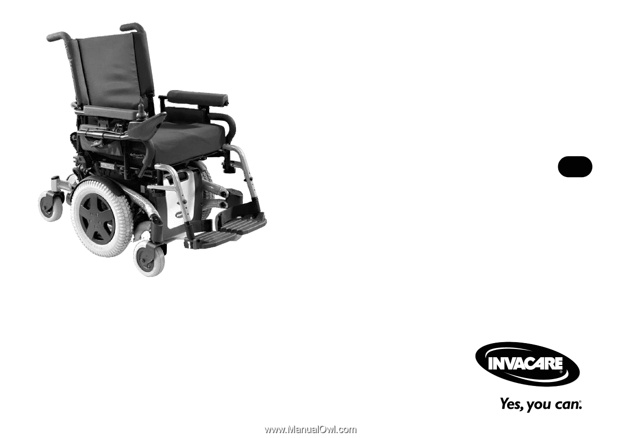
User Manual
This manual MUST be given to the user of the product.
BEFORE using this product, read this manual and save for future reference.
EN
Invacare
®
TDX
®
SP, TDX
SR
Power Wheelchair Base