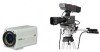
JVC KY-F560U KY-F560U Multi-purpose camera 48 page instruction manual - Page 10
GENLOCK IN] External Sync Signal, Slot Cover for Option Cards
 |
UPC - 046838326004
View all JVC KY-F560U manuals
Add to My Manuals
Save this manual to your list of manuals |
Page 10 highlights
1. Getting Started (continued) Part Names and Functions (continued) Back 9 15 AW BARS MENU SET REMOTE LENS GENLOCK IN VIDEO OUT DC IN POWER SEE INSTRUCTION MANUAL 10 11 12 14 13 9 [REMOTE] Remote Terminal (Mini DIN 6 Pin, Female) Terminal for connection to remote control unit (RM-LP55 or RM-LP57, both sold separately). ☞ Page 11 'Description of Terminals' ☞ Page 44 'Connecting the Remote Control Unit' 0 [LENS] Lens Connection Terminal Connect the lens cable. ☞ Page 11 'Description of Terminals' ☞ Page 14 'Mounting the Lens' ! [VIDEO OUT] Video Signal Output Terminal Output terminal for composite video signals. Connect to video input terminals such as monitors or switchers. @ [POWER] Power Indicator Light Lights up when power is supplied to this unit. # [DC IN] Power Input Terminal (Mini DIN 8 Pin, Female) Power of this unit (DC 12 V) is supplied through this terminal. Use an AC adaptor (AA-P700) for the power supply. ☞ Page 11 'Description of Terminals' ☞ Page 15 'Connecting the Power Supply' $ [GENLOCK IN] External Sync Signal Input Terminal Reference signal input terminal for synchronization with this unit. Inputs composite video signals or black burst signals. % Slot Cover for Option Cards Remove the cover to install the option card. ☞ Page 46 'Connecting Optional Devices' Please consult your JVC-authorized dealer on optional devices. 10
-
 1
1 -
2
-
3
-
4
-
 5
5 -
 6
6 -
 7
7 -
 8
8 -
 9
9 -
 10
10 -
 11
11 -
 12
12 -
 13
13 -
 14
14 -
 15
15 -
16
-
17
-
18
-
19
-
20
-
21
-
22
-
23
-
24
-
25
-
26
-
27
-
28
-
29
-
30
-
31
-
32
-
33
-
34
-
35
-
36
-
37
-
38
-
39
-
40
-
41
-
42
-
43
-
44
-
45
-
46
-
47
-
48
 |
 |
