Kenwood TH-D74A User Manual - Page 14
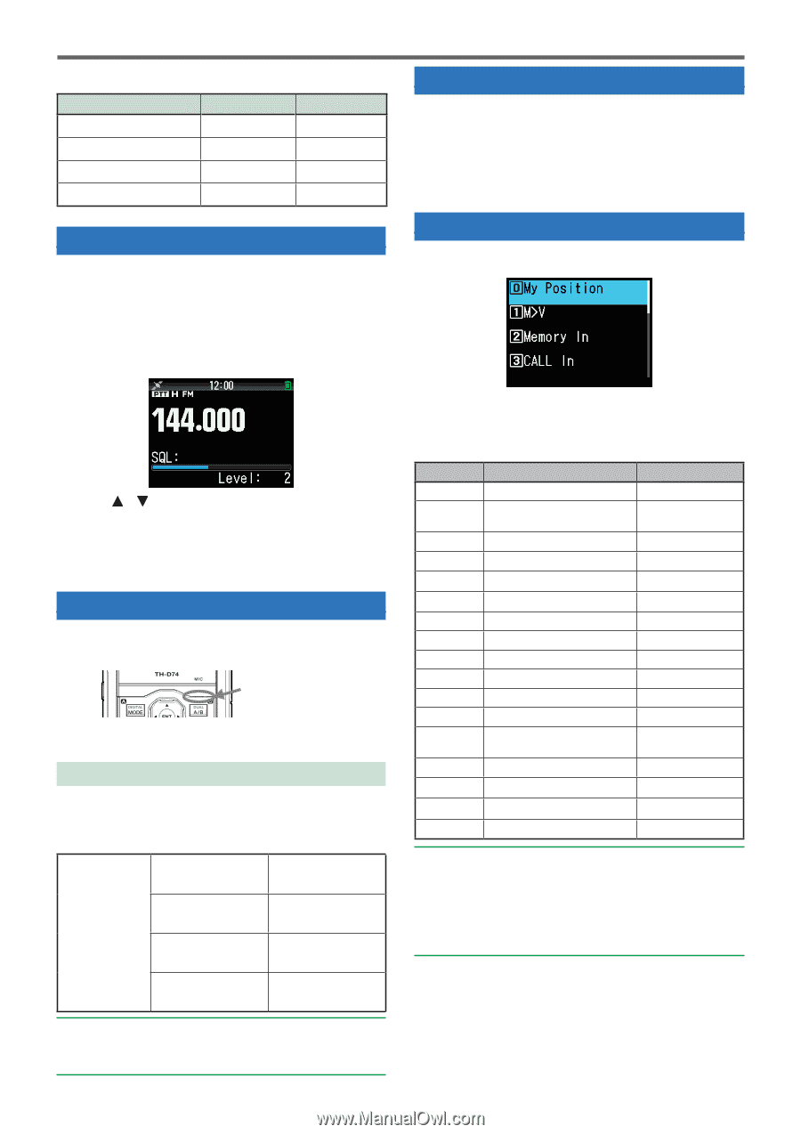
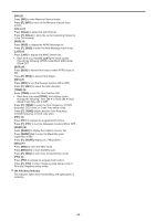
Adjusting The Squelch, Transmitting, Monitor, Function Select Mode, Selecting An Output Power
 |
View all Kenwood TH-D74A manuals
Add to My Manuals
Save this manual to your list of manuals |
Page 14 highlights
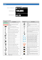
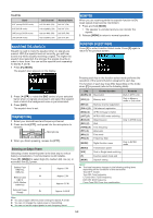
TH-D74E Band VHF (except DV/DR mode) VHF(DV/DR mode) UHF(except DV/DR mode) UHF(DV/DR mode) Call Channel Memory Name 145.500 MHz (FM) Call VHF (FM) 144.8125MHz (DV) Call VHF (DV) 433.500 MHz (FM) Call UHF (FM) 433.6125MHz (DV) Call UHF (DV) ADJUSTING THE SQUELCH Squelch is used to mute the speaker when no signals are present. With the squelch level set correctly, you will hear sound only while actually receiving a signal. The higher the squelch level selected, the stronger the signals must be in order to hear them. You can set the squelch level separately for Bands A and B. 1 Press [F], [MONI]. The squelch level appears on the display. MONITOR When you are receiving while the squelch function is ON, weak signals may become intermittent. 1 Press and hold [MONI]. • The speaker is unmuted and you can monitor the signals. 2 Release [MONI] to return to normal operation. FUNCTION SELECT MODE Press [F] to enter Function Select mode. Press [F] again to return to the previous screen. 2 Press [ ]/[ ] or rotate the ENC control of your selected band, when no signals are present, and select the squelch level at which the background noise is just eliminated. 3 Press [ENT]. The squelch level is set. TRANSMITTING 1 Select your desired band and frequency/channel. 2 Press and hold [PTT], and speak into the microphone to transmit. Microphone 3 When you finish speaking, release the [PTT]. Selecting an Output Power Selecting a lower transmit power is the best way to reduce battery consumption, if communication is still reliable. Press [F], [MENU] to select high (H), medium (M), low (L), or economic low (EL) power. Battery Pack KNB-75L H KNB-74L Battery Case M KBP-9 (AAA Alkaline batteries) L Approx. 5 W Approx. 2 W Approx. 0.5 W External Power Supply EL Approx. 0.05 W Note: ◆◆ You can program different power settings for bands A and B. ◆◆ You can not change the output power in transmitting. ◆◆ You can not set the output power in each frequency band. Pressing each key in the function select mode performs the operation of the second function assigned to each key. The function of each key may differ depending on the mode when [F] is pressed (refer to the following table). Key Second function [MARK] (0) My position [VFO] (1) Memory shift Remarks Built-in GPS is On. Only in Memory mode or Call mode [MR] (2) Memory channel registration [CALL] (3) Call channel registration [MSG] (4) APRS message creation [LIST] (5) APRS/ KISS mode switching [BCN] (6) [REV] (7) [TONE] (8) [PF1] (9) [MHz] (*) [PF2] (#) Object beacon Shift Tone frequency Attenuator Fine mode Frequency Step [MODE] Digital function menu [MENU] Transmission power Only in APRS mode Only in DV/DR mode [A/B] Dual or Single band switching [F] Function select mode end [MONI] Squelch setting Note: ◆◆ The tone frequency changes to the following setting items depending on the conditions of this transceiver. Tone OFF: Invalid Tone ON: Tone frequency CTCSS ON: CTCSS frequency DCS ON: DCS frequency Cross Tone ON: Cross tone combination 5-3
-
 1
1 -
2
-
3
-
4
-
5
-
6
-
7
-
8
-
 9
9 -
 10
10 -
 11
11 -
 12
12 -
 13
13 -
 14
14 -
 15
15 -
 16
16 -
 17
17 -
 18
18 -
 19
19 -
20
-
21
-
22
-
23
-
24
-
25
-
26
-
27
-
28
-
29
-
30
-
31
-
32
-
33
-
34
-
35
-
36
-
37
-
38
-
39
-
40
-
41
-
42
-
43
-
44
-
45
-
46
-
47
-
48
-
49
-
50
-
51
-
52
-
53
-
54
-
55
-
56
-
57
-
58
-
59
-
60
-
61
-
62
-
63
-
64
-
65
-
66
-
67
-
68
-
69
-
70
-
71
-
72
-
73
-
74
-
75
-
76
-
77
-
78
-
79
-
80
-
81
-
82
-
83
-
84
-
85
-
86
-
87
-
88
-
89
-
90
-
91
-
92
-
93
-
94
-
95
-
96
-
97
-
98
-
99
-
100
-
101
-
102
-
103
-
104
-
105
-
106
-
107
-
108
-
109
-
110
-
111
-
112
-
113
-
114
-
115
-
116
-
117
-
118
-
119
-
120
-
121
-
122
-
123
-
124
-
125
-
126
-
127
-
128
-
129
 |
 |