Kenwood TS-2000 Operation Manual - Page 105
MCP AND TNC, ACC 2
 |
View all Kenwood TS-2000 manuals
Add to My Manuals
Save this manual to your list of manuals |
Page 105 highlights
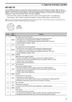
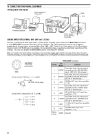
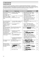
16 CONNECTING PERIPHERAL EQUIPMENT MCP AND TNC Use the ACC 2 connector to connect the input/output lines from a Terminal Node Controller (TNC) for Packet operation, a Multimode Communications Processor (MCP) for operation on Packet, PacTOR, AMTOR, G-TORTM, PSK31, or FAX, or from a Clover interface. Also use the ACC 2 connector to connect SSTV and phone patch equipment (1 male ACC2 connector (E07-1351-XX) is supplied). • Connect the TNC or MCP to the ACC 2 connector using a cable equipped with a 13-pin DIN plug. • Connecting the TNC or MCP to a personal computer or dumb terminal requires an RS-232C cable. Note: Do not share a single power supply between the transceiver and the TNC or MCP. Keep as wide a separation as possible between the transceiver and the computer to reduce noise-pickup by the transceiver. 13 9 10 11 12 56 78 12 34 ACC2 Front view (Rear panel) Pin No. 1 Pin Name SANO Function AF output from the sub-receiver • Connect to the TNC or MCP receive data pin for digital operation. • AF output level is independent from SUB AF control setting. • AF output level can be changed by adjusting the Menu No. 50D value. • Output impedance: Approx. 10kΩ. 2 RTTY RTTY key input AF output from the main transceiver • Connect to the TNC or MCP receive data pin for digital operation. 3 MANO • AF output level is independent from the MAIN AF control setting. • AF output level can be changed by adjusting the Menu No. 50C value. • Output impedance: Approx. 10kΩ. 4 GND Ground Main transceiver squelch control • Connect to the TNC or MCP squelch control pin for digital operation. 5 MSQ • Prevents the TNC from transmitting while the transceiver squelch is open. • Squelch open: Low impedance • Squelch closed: High impedance 6 NC No connection Sub-receiver squelch control • Connect to the TNC or MCP squelch control pin for digital operation. 7 SSQ • Prevents the TNC from transmitting while the transceiver squelch is open. • Squelch open: Low impedance • Squelch closed: High impedance 8 GND Ground Transceiver PTT line control 9 PKS • Ground this terminal to transmit. • Connect to the TNC or MCP transmit/ receive switching pin for digital operation. • Microphone audio input mutes when the transceiver transmits. 10 NC No connection 11 PKD Microphone audio input • Connect to the TNC or MCP transmit data pin for digital operation. 12 GND Ground PTT control 13 SS • Ground this terminal to transmit. • For connecting a footswitch or other external controller (in parallel with MIC jack). • Microphone audio input does NOT mute when the transceiver transmits. 95
-
 1
1 -
2
-
3
-
4
-
5
-
6
-
7
-
8
-
9
-
10
-
11
-
12
-
13
-
14
-
15
-
16
-
17
-
18
-
19
-
20
-
21
-
22
-
23
-
24
-
25
-
26
-
27
-
28
-
29
-
30
-
31
-
32
-
33
-
34
-
35
-
36
-
37
-
38
-
39
-
40
-
41
-
42
-
43
-
44
-
45
-
46
-
47
-
48
-
49
-
50
-
51
-
52
-
53
-
54
-
55
-
56
-
57
-
58
-
59
-
60
-
61
-
62
-
63
-
64
-
65
-
66
-
67
-
68
-
69
-
70
-
71
-
72
-
73
-
74
-
75
-
76
-
77
-
78
-
79
-
80
-
81
-
82
-
83
-
84
-
85
-
86
-
87
-
88
-
89
-
90
-
91
-
92
-
93
-
94
-
95
-
96
-
97
-
98
-
99
-
 100
100 -
 101
101 -
 102
102 -
 103
103 -
 104
104 -
 105
105 -
 106
106 -
 107
107 -
 108
108 -
 109
109 -
 110
110 -
111
-
112
-
113
-
114
-
115
-
116
-
117
-
118
-
119
-
120
-
121
-
122
-
123
-
124
-
125
-
126
-
127
-
128
-
129
-
130
-
131
-
132
-
133
-
134
-
135
-
136
-
137
-
138
-
139
-
140
-
141
-
142
-
143
-
144
-
145
-
146
-
147
-
148
-
149
-
150
-
151
-
152
-
153
-
154
-
155
-
156
 |
 |
