Kenwood TS-2000 Operation Manual - Page 106
Connecting Peripheral Equipment, Typical Mcp/ Tnc Setup, Linear Amplifier 50 Mhz, Vhf, Uhf And 1.2 Ghz
 |
View all Kenwood TS-2000 manuals
Add to My Manuals
Save this manual to your list of manuals |
Page 106 highlights
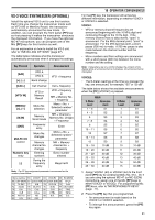
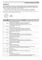
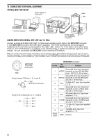
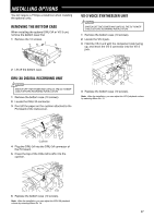
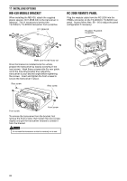
16 CONNECTING PERIPHERAL EQUIPMENT TYPICAL MCP/ TNC SETUP Power supply for TNC/ MCP Black Red Personal computer TNC/MCP TS-2000 TS-2000X TS-2000B LINEAR AMPLIFIER (50 MHz, VHF, UHF and 1.2 GHz) Power supply for TS-2000(X)/ TS-B2000 Connect an external 50 MHz/ VHF/ UHF/ 1.2 GHz power amplifier control cable to the EXT.CONT connector (1 male EXT.CONT connector (E07-0851-XX) is supplied). The TX/RX switching time can be configured independently for each band, accessing Menu Nos. 28B ~ 28E. Select 1 for 10 ms delay or 2 for 25 ms delay. However, when CW Full Break-in is enabled, 10 ms switching delay is applied automatically regardless of the settings. You can also disable the EXT.CONT control, selecting OFF (default). Note: The TX/RX control method differs, depending on external amplifier models. Most amplifiers enter the TX mode when the control terminal is grounded. For those amplifiers, connect the metal cover of the EXT.CONT connector to the GND terminal of the amplifier and connect pin 2 (50 MHz), pin 6 (144 MHz), pin 1 (430/ 440 MHz), or pin 4 (1.2 GHz) of the connector to the control terminal of the amplifier. rwt qye ui EXT.CONT Front view (Rear panel) GND Circuit of each TXC (pin 1, 2, 4, and 6) C TXC B (20 V DC, 20 mA max.) E Circuit of ALC inputs (pin 3, 5, 7, and 8) pin 3 pin 5 pin 7 pin 8 EXT.CONT connector Pin No. Pin Name Function Grounded when the transceiver 1 43TXC transmits on the 430/ 440 MHz band. (DC 20 V, 20 mA max.) Grounded when the transceiver 2 50TXC transmits on the 50 MHz band. (DC 20 V, 20 mA max.) 3 ALC 50 MHz ALC input from amplifier (-7 V). Grounded when the transceiver 4 12TXC transmits on the 1.2 GHz band. (DC 20 V, 20 mA max.) 5 ALC 430 (440) MHz ALC input from amplifier (-7 V). Grounded when the transceiver 6 14TXB transmits on the 144 MHz band. (DC 20 V, 20 mA max.) 7 ALC 1.2 GHz ALC input from amplifier (-7 V). 8 ALC 144 MHz ALC input from amplifier (-7 V). Metal cover GND Ground 96
-
 1
1 -
2
-
3
-
4
-
5
-
6
-
7
-
8
-
9
-
10
-
11
-
12
-
13
-
14
-
15
-
16
-
17
-
18
-
19
-
20
-
21
-
22
-
23
-
24
-
25
-
26
-
27
-
28
-
29
-
30
-
31
-
32
-
33
-
34
-
35
-
36
-
37
-
38
-
39
-
40
-
41
-
42
-
43
-
44
-
45
-
46
-
47
-
48
-
49
-
50
-
51
-
52
-
53
-
54
-
55
-
56
-
57
-
58
-
59
-
60
-
61
-
62
-
63
-
64
-
65
-
66
-
67
-
68
-
69
-
70
-
71
-
72
-
73
-
74
-
75
-
76
-
77
-
78
-
79
-
80
-
81
-
82
-
83
-
84
-
85
-
86
-
87
-
88
-
89
-
90
-
91
-
92
-
93
-
94
-
95
-
96
-
97
-
98
-
99
-
100
-
 101
101 -
 102
102 -
 103
103 -
 104
104 -
 105
105 -
 106
106 -
 107
107 -
 108
108 -
 109
109 -
 110
110 -
 111
111 -
112
-
113
-
114
-
115
-
116
-
117
-
118
-
119
-
120
-
121
-
122
-
123
-
124
-
125
-
126
-
127
-
128
-
129
-
130
-
131
-
132
-
133
-
134
-
135
-
136
-
137
-
138
-
139
-
140
-
141
-
142
-
143
-
144
-
145
-
146
-
147
-
148
-
149
-
150
-
151
-
152
-
153
-
154
-
155
-
156
 |
 |
