LG 37LC2R Owners Manual - Page 27
When connecting with a D-sub 15 pin cable
 |
View all LG 37LC2R manuals
Add to My Manuals
Save this manual to your list of manuals |
Page 27 highlights
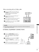
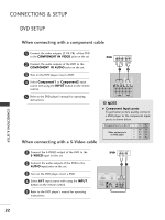
COMPONENT IN 2 VIDEO 1 AUDIO HDMI RGB IN AV OUT AV IN 1 When connecting with a D-sub 15 pin cable ( ) S-VIDEO VIDEO AUDIO RGB IN 1 Connect the RGB outAVpOUuT t of the digital set-top box to the RGB IN (PC/DTV) jack on the set. AV IN 1 ( ) S-VIDEO VIDEO AUDIO 2 Connect the audio outputs of the set-top box to the AUDIO (RGB/DVI) jack on the set. (R) AUDIO (L) RGB-DTV OUTPUT Digital Set-top RGB IN RGB (PC/DTV) AUDIO AV OUT Box RS-232C IN (CONTROL & SERVICE) AV IN 1 2 1 SS-V-VIDIDEEOO VIDEO ( ) AUDIO 3 Turn on the digital set-top box. (Refer to the owner's manual for the digital set-top box.) 4 Select RGB-DTV input source with using the INPUT button on the remote control. RGB IN RGB (PC/DTV) AUDIO (RGB/DVI) AV OUT RS-232C IN (CONTROL & SERVICE) AV IN 1 SS-V-VIDIDEEOO VIDEO (MONO) AUDIO HDM HDMI/DVI IN When connecting with a HDMI cable CONNECTIONS & SETUP 1 Connect the HDMI output HDMI/DVIIN of the digital set-top box to the HDMI /DVI IN jack on the set. 2 Select HDMI /DVI input source with using the INPUT button on the remote control. 3 Turn on the digital set-top box. (Refer to the owner's manual for the digital set-top box.) REMOTE CONTROL IN HDMI/DVI IN 1 D i g i t a l S e t - t o p B o x HDMI/DVI IN HDMI-OUTPUT ! NOTE G TV can receive the video and audio signal simultaneously with using a HDMI cable. G If the digital set-top box supports Auto HDMI function, output resolution of the digital set-top box will be automatically set to 1280x720p. G If the digital set-top box does not support Auto HDMI, you need to set the output resolution appropriately. To get the best picture quality, adjust the output resolution of the digital set-top box to 1280x720p. VARIABLE AUDIO OUT COMPONENT IN 2 VIDEO 1 AUDIO ANTENNA IN VARIABLE AUDIO OUT VARIABLE AUDIO OUT COMPONENT IN COMPONENT IN 2 1 ANTENNA IN 25
-
 1
1 -
2
-
3
-
4
-
5
-
6
-
7
-
8
-
9
-
10
-
11
-
12
-
13
-
14
-
15
-
16
-
17
-
18
-
19
-
20
-
21
-
 22
22 -
 23
23 -
 24
24 -
 25
25 -
 26
26 -
 27
27 -
 28
28 -
 29
29 -
 30
30 -
 31
31 -
 32
32 -
33
-
34
-
35
-
36
-
37
-
38
-
39
-
40
-
41
-
42
-
43
-
44
-
45
-
46
-
47
-
48
-
49
-
50
-
51
-
52
-
53
-
54
-
55
-
56
-
57
-
58
-
59
-
60
-
61
-
62
-
63
-
64
-
65
-
66
-
67
-
68
-
69
-
70
-
71
-
72
-
73
-
74
-
75
-
76
-
77
-
78
-
79
-
80
-
81
-
82
-
83
-
84
-
85
-
86
-
87
 |
 |
